Table of Contents
Venting/pumping FP chamber & emptying/filling gaseous detectors
In June 2019, a new Turbo Pump with magnetically-levitating bearings (Leybold MAG 2200iP) was installed in the S800 focal-plane chamber. This pump has a dry-N line connected to it that is purging continuously the bearings. This creates an extra pressure in the foreline, which must be pumping down continuously. Therefore, it is critical turn off the turbo pump whenever the foreline valve needs to be closed.
The GHS for the focal plane is operated remotely through CS studio. Its page can be found on the EXP network through FRIB EXP Main → S800 → GHS Pages (Secondary Pages) → FP Main Page and is shown below.

Here are screenshots of the “FP_State_Buttons” page for the CRDC (left) and Ion Chamber (right). Currently in “PUMP status.


Instructions on how to vent/pump-down the focal-plane chamber and empty/fill and run detectors are described below.
Emptying Detectors
- Check that the system is in RUN mode on the “FP_State_Buttons” page under FRIB EXP Main → S800 → GHS Pages (Secondary Pages)
- Return to “GHS_FP_Main” click Enable MFC Controls
- Set MFC1 to 0 sccm to stop the flow of P10 to the IC vessel
- Set MFC2 to 0 sccm. This will cause MFC3 to also go to zero through the ratio control. The flow of iC4H10 and CF4 to the CRDC chamber will cease.
- Click Enable Controls for the CRDC and IC Control Valve PIDs and then click DISABLE for each of them. This will open the control valve to 100% for each vessel and begin pumping them out.
- The IC vessel has a much larger quantity of gas compared to the CRDC vessel. In order to pump them out at a similar speed go to the “FP_State_Buttons” page and go to the D2708 (Ion Chamber) tab. Click EMPTY. This will more rapidly pump down the IC vessel. Both vessels should be emptied at about the same time.
- Open a data browser and plot the PVs for PT1 (S800_GHS:CMG_D2708A:VP_RD) and PT2 (S800_GHS:CMG_D2703A:VP_RD).
- Wait for PT1 and PT2 to read < 0.5 Torr. This should take about 30 minutes.
- Open the Focal Plane VAC D2686 page (FRIB EXP Main → S800 → Vacuum Main → Focal Plane).
- Ensure the beamline gate valve to the FP chamber is closed (BGV_D2671).
- Ensure IG_D2686 is off.
- Notify the Control Room that EXP alarms may occur.
- On the “FP_State_Buttons” page, click VENT mode for both D2703 (CRDCs) and D2708 (Ion Chamber).
- The detector volumes will be bypassed to the chamber. The TGV and TMP should handle the gas load and quickly pump the chamber back to high vacuum. If any issues occur, contact the Rare Isotope Operations Vacuum Group.
- The IG may turned back on once the BPG reads < 5 mTorr.
- The GHSs can remain in this state until they need to be filled again.
Venting FP Chamber
Notify the Control Room that you will vent the FP chamber.
- Ensure the IG in the Focal Plane Pumping Station is off. This page can be found in FRIB EXP Main → S800 → Vacuum Main (Primary Pages) → Focal Plane.
- Check the box next to “Valve Controls”, then click Close next to the Turbo Gate Valve (TGV).
- Turn the TMP off.
- Ensure both CRDCs and IC are in *VENT* mode
- Plot PT1 (S800_GHS:CMG_D2708A:VP_RD), PT2 (S800_GHS:CMG_D2703A:VP_RD), and PT3 (S800_GHS:CMG_D2708C:VP_RD) from the “GHS_FP_Main” page as well as BPG (RBT_BTS34:BPG_D2686:VP_RD) from the “D2686 Pumping Station” page on the same axis.
- Briefly (~1 second) open the vent valve by clicking Open next to the valve labeled “Vent” then click Close. Check that all the pressures are increasing at the same rate.
- Again, open the vent valve and observe the pressure for 30 seconds to ensure the pressures are increasing at the same rate among all four gauges. If a difference of > 2 Torr is observed between any two gauges, click Close on the vent valve.
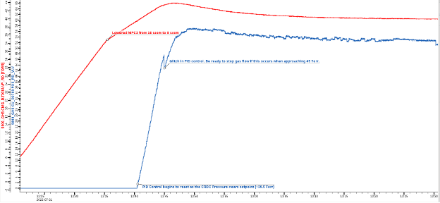
- Allow the pressure to rise to ~735 Torr (~45 min). The vent valve should close itself at 735 Torr but be ready to close it manually if an error occurs.
The CRDC (Purple) and IC (Green) vessel pressures during Emptying and Venting procedures outlined above are shown below.

Pumpdown of FP Chamber
- Open “Focal Plane Pumping Station” page from FRIB EXP Main → S800 → Vacuum Main (Primary Pages).
- Open “GHS_FP_Main” and “FP_State_Buttons” pages from FRIB EXP Main → S800 → GHS Pages (Secondary Pages).
- Plot PT1 (S800_GHS:CMG_D2708A:VP_RD), PT2 (S800_GHS:CMG_D2703A:VP_RD), and PT3 (S800_GHS:CMG_D2708C:VP_RD) from the “GHS_FP_Main” page as well as BPG (RBT_BTS34:BPG_D2686:VP_RD) from the “D2686 Pumping Station” page on the same axis.
- On the “FP_State_Buttons” page change from “Vent” mode to “Pump” mode by clicking PUMP in both the D2703 (CRDC) and D2708 (IC) tabs.
- Check the box next to “Valve Controls” on the “Focal Plane VAC D2686” page.
- Ensure the TMP is off and Foreline Valve (FV) is closed. Open the Roughing Valve (RV) briefly (2 seconds) by clicking Open and observe the behavior of the pressure gauges. If they all decrease at the same rate, again click Open to begin roughing out the chambers.
- When the BPG reads < 300 mTorr, Close RV and Open FV. Turn the TMP on. When the TMP is “at speed”, Open the TGV.
- Once the BPG reads < 5 mTorr, the IG may be turned on.
Filling & Running Detectors
- Ensure that the FP chamber is under high vacuum, detectors are bypassed to the chamber, and detector gas bottles are open.
- On the “FP_State_Buttons” page click RUN on both D2703 (CRDC) and D2708 (Ion Chamber) tabs.
- Plot PT1 (S800_GHS:CMG_D2708A:VP_RD), PT2 (S800_GHS:CMG_D2703A:VP_RD), and the control valves for both D2703 (CRDC, S800_GHS:CV_D2703:POS_RD_VLV) and D2708 (IC, S800_GHS:CV_D2708:POS_RD_VLV).
- Click Enable Controls for the CRDC and IC “Control Valve PID”s, then click ENABLE to turn on PID controls for each vessel. Each control valve should adjust to its BASE value.
- If the CRDC valve remains completely open (stuck at 100%), open a probe with PV: “S800_GHS:CV_D2703:MODE_CSET_PVC”. In the “New Value” box, enter “CLOSE” and press enter. If the valve then closes (100% to 0%), enter “AUTO” in the “New Value” box and press enter. This should reenable PID control.
- Click Enable MFC Controls.
- Set MFC1 to 25 sccm. Ensure PT1 begins to increase in pressure.
- Set MFC2 to 8 sccm. Ensure MFC3 automatically sets to 32 sccm and PT2 begins to increase in pressure.
- The IC vessel is a much larger chamber than the CRDC vessel and needs to reach a higher operating pressure. In order to fill the vessel in a timely manner it is safe to override the MFC and set it to “Fully Open”. To do this select “Fully Open MFC” in the dropdown menu next to MFC1.
- If desired, the CRDC vessel can be filled with MFC2 set to 16 sccm. Be ready to decrease MFC2 back to 8 sccm at 35 Torr as the PID controls are not calibrated to prevent the vessel from overpressurizing at this increased flow. Allow the CRDC vessel to slowly approach 40 Torr.
- If CSET is not set to 40 Torr, decrease MFC2 at 5 Torr below the setpoint.
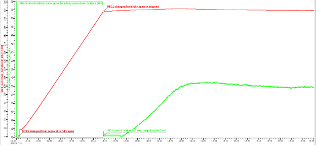
- As the vessels approach their setpoints the Control Valves should begin to increase from their BASE values in order to equalize the pressure around the setpoint. Note that the CRDC pressure will change much faster than the IC pressure and has a much smaller tolerance. If PT2 reaches 45 Torr the system will immediately enter “EMPTY” mode to prevent the foil disc from bursting. Use the figure below for reference.
- If PT2 reaches 44 Torr and the control valve is not open enough to start decreasing the pressure, immediately set MFC2 to 0 sccm and allow the valve to begin decreasing the pressure before resetting MFC2 back to 8 sccm. Notify the Rare Isotope Operations Vacuum Group. Continue to monitor the pressure and control valve behavior to ensure the PID is in control of the pressure.
- Once PT1 reaches 300 Torr, adjust MFC1 back to 25 sccm by selecting “Go to MFC Setpoint” in the dropdown menu next to MFC1. The pressure will equilibrate down to about 299.5 Torr. Allow the IC vessel to slowly approach 300 Torr. Use the figure below for reference.
- If CSET is not set to 300 Torr, adjust MFC1 back to 25 sccm when the setpoint is reached.
- The control valve for the IC vessel is set to react slowly as the vessel has a long pressure period. The valve will not “wake up” until 300 Torr is reached on PT1. This is okay as long as the control valve begins to open by this point. The pressure change is slow enough that over the next hour the valve will open enough to catch the pressure before it exceeds 305 Torr, well within the operating limit (500 Torr).
- The PID controls for each vessel are calibrated to maintain their respective setpoints to within +/- 0.1 Torr. If the operator notices a larger variation after an hour of PID control, notify the Rare Isotope Operations Vacuum Group.


Zeroing PTs
- When readings of the capacitance manometers (PT1 [S800_GHS:CMG_D2708A:VP_RD], PT2 [S800_GHS:CMG_D2703A:VP_RD], and PT3 [S800_GHS:CMG_D2708C:VP_RD]) are off (e.g. 1 Torr when pumped down), these need to be zeroed.
- Before “zeroing” a pressure gauge. Make sure it is completely bottomed out. This would correspond to the GHS being in “Vent” mode and the TMP being on. If the IG is on and shows that the system is under High Vacuum (<10-3 Torr) you can go ahead and zero the gauge.
- Here are instructions with screenshots by Josh:
- The relevant PVs are “ZERO_CMD” instead of “VP_RD”, e.g. S800_GHS:CMG_D2708A:ZERO_CMD for PT1. Send “1” to zero these PTs.


Opening/closing FP chamber
Instructions on how to open/close the focal-plane chamber are described below.
Open focal-plane chamber
- After venting the FP chamber, the pressure inside the chamber is slightly above atmospheric due to the dry N2 pumped. Before opening the chamber, it is recommended to vent the extra N2 by “forcing” the pressure-relief valve with e.g. a screwdriver

- Unlock the padlock protecting the power brakers of the switch controls to open the chamber, and press the START button

- Turn the switch to open the clamps holding the FP chamber. The weight held by the hydraulic piston will increase


- Turn on the switch to activate the motor opening the chamber. It takes about 10 minutes to get the chamber totally opened


Closing focal-plane chamber
- Turn the switch to move the chamber to position “UP”, and keep it that way for about 10 minutes (the time it takes the chamber to be closed)
- Check the display indicating the weight lift by the hydraulic system. When the chamber is close, the weight displayed will increase drastically due to the resistance experienced by the hydraulic system. At that point, stop immediately the lifting switch (otherwise, a weight-limit set point might be reached, disabling the hydraulic system)
- Turn the knob to close the clamps
- Inspect the clamps and chamber flange (no gaps) to ensure that the chamber is properly sealed
- Before pumping the chamber down, make sure that the scintillator is properly connected. This can be done by biasing the detector and checking the signals, either from the scalers or with a scope. One should clearly see cosmic rays; if that is not the case, the phototubes are likely misconnected.
Installing FP scintillator
Instructions on how to install the focal-plane scintillator are described below.
- The figure below shows the FP chamber open, with the “old” FP scintillator to be replaced by the new one

- Unplug the bases of the up and down phototubes. The platic tie holding the cable of the up phototube to the chamber needs to be cut


- Using an allen wrench, unscrew the two bolts attaching the scintillator frame to the base of the chamber
 .
. - Climb to the chamber and pull the scintillator frame up. Once unplugged, handle it to a second person

 .
. - With the help of a second person, hold the new scintillator by its frame and place it in the right spot. A second person should be ready to screw the frame to the base of the chamber.
- Connect the bases of the up and down phototubes. The latter is quite difficult because one cannot see the pins
- Using a plastic tie, attach the cable of the up phototube to the scintillator frame


