installation_fp_sci
This is an old revision of the document!
Table of Contents
Installation of focal-plane scintillator
Vent focal-plane chamber
- Open the HV Remote Control GUI and ensure that the focal-plane detectors are unbiased
- Open the Labview gas handling system and verify that there is no gas in the CRDCs and IC. Open valves 4 (IC supply), 5 (IC bypass), 6 (IC focal-plane bypass), 20 (CRDC supply), 21 (CRDC bypass), and 22 (CRDC focal-plane bypass). The rest of the valves should be closed
- Ensure that the FP ion gauge (I264IG) is off (see details here)
- Open PanelMate and select S800vac file in directory \\exp\files\control\ncsdata\General\Qt\Templates. Go to page 07, and ensure that I265GV (gate valve separating FP box from rest of beam line) is closed.
- Click on the VENT STATUS window and begin the venting procedure. The VENT VALVE I260VV window will turn red and display “OPEN”. The pressure should remain constant because the manual venting valve is still closed
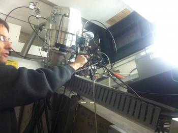
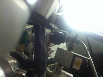
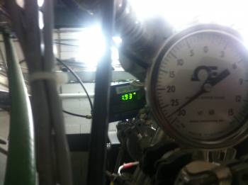
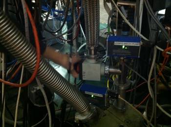
- Gently open the manual venting valve until the pressure displayed in the Pirani Gauge (see figure below) increases by ~1 torr every 15 seconds (see figures below)
- Wait until the chamber is vented (few hours). The I261PG Pirani Gauge should read slightly above atmospheric pressure (due to the dry N2 flow pumped to the chamber). The window VENT STATUS in PanelMate should display “VENT VALVE OPEN”. The window PUMPDOWN STATUS should display “PUMPDOWN STOPPED”
- When the chamber is fully vented, select VENT STATUS and click STOP VENTING PROCEDURE. This will automatically close the vent valve I260VV
- Close the manual vent valve
Open focal-plane chamber
Installing FP scintillator
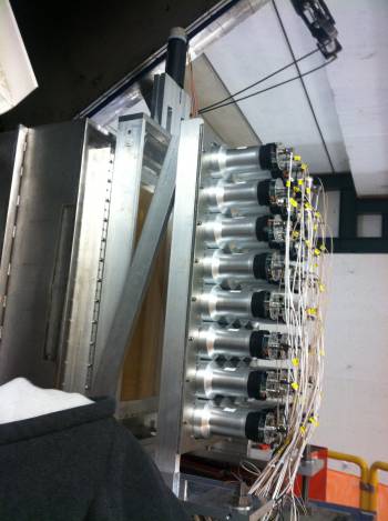
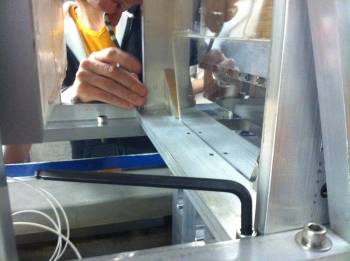
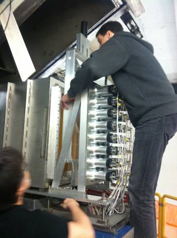
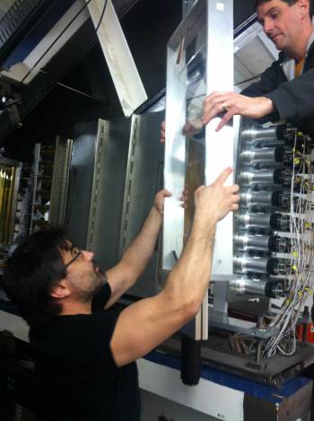
- With the help of a second person, hold the new scintillator by its frame and place it in the right spot. A second person should be ready to screw the frame to the base of the chamber
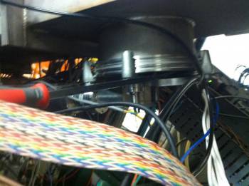
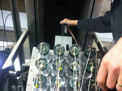
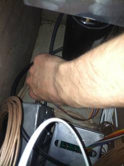
- Connect the bases of the up and down phototubes. The later is quite difficult because one cannot see the pins
- Using a plastic tie, attach the cable of the up phototube to the scintillator frame
Closing focal-plane chamber
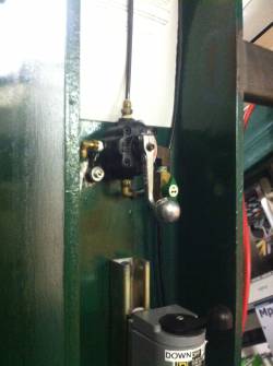
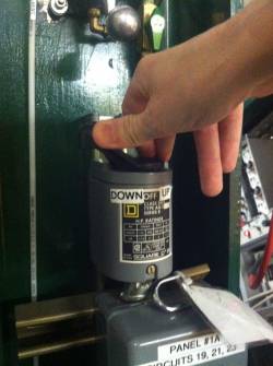
- Turn the switch to move the chamber to position “UP”, and keep it that way for about 10 minutes (the time it takes the chamber to be closed)
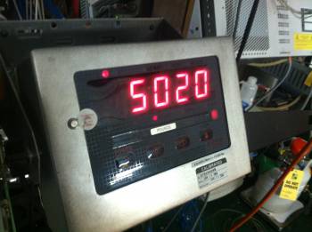
- Check the display indicating the weight lift by the hydraulic system. When the chamber is close, the weight displayed will increase drastically due to the resistance experienced by the hydraulic system. At that point, stop immediately the lifting switch (otherwise, a weight-limit set point might be reached, disabling the hydraulic system)
- Turn the knob to close the clamps
- Inspect the clamps and chamber flange (no gaps) to ensure that the chamber is properly sealed
- Before pumping the chamber down, make sure that the scintillator is properly connected. This can be done by biasing the detector and checking the signals, either from the scalers or with a scope. One should clearly see cosmic rays; if that is not the case, the phototubes are likely miss connected
Pumping focal-plane chamber
- Make sure that the pressure-relief valve and the manual vent valve (see above) are closed.
- Open PanelMate S800vac and go to page 07. Make sure
- Select window PUMPDOWN STATUS and click on button START PUMPDOWN. The PUMPDOWN STATUS and VENT STATUS windows should display “PUMPDOWN IN PROGRESS”
- Wait for some hours until vacuum is good
installation_fp_sci.1497993403.txt.gz · Last modified: 2017/06/20 17:16 by pereira

