This is an old revision of the document!
Table of Contents
S800 SpecTcl
SpecTcl is the NSCL's event data analysis tool used for online and offline data analysis during experiments involving the S800 spectrograph. The documentation is accessible at: http://docs.nscl.msu.edu/daq/spectcl/
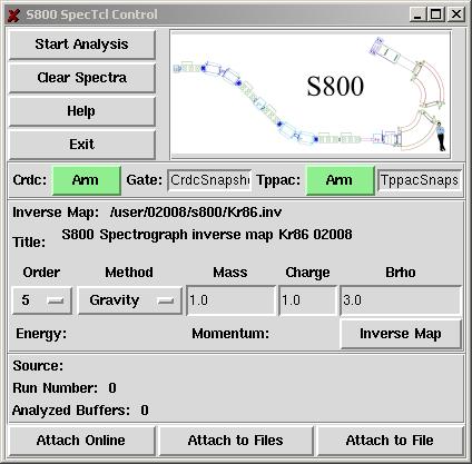
The SpecTcl Control has been adapted for special functions required for the analysis of S800 data. Fig xxx shows the GUI control of the S800 analysis.
The inverse map which enables the trajectory reconstruction of the particles within the spectrograph beam line can be loaded. Snapshots of CRDC and TPPAC events sampled in the pads and strips can be viewed. If this option is “armed”, the sample is read out for the first event that falls into the specified gate. This is a diagnostics tool to analyze the response of the CRDCs and TPPACs.
The TreeParameter class
The TreeParameter class provides a mean to implement parameters in SpecTcl in a tree-like structure and without the need to specify parameter identification numbers. The parameters are referred to by their names only, which at the same time indicate their location in the tree. This reference mechanism is valid for both the coding part of SpecTcl (C++ code) and the interpreter part (Tcl/Tk shell). It eliminates the confusion induced by the use of numerals to refer to the parameters, and allows the user to organize the parameters in a logical fashion.
Frequently used parameters for S800 SpecTcl
- s800.fp.ic.sum: energy loss measured with the ion chamber
- s800.fp.crdc1 s800.fp.crdc2
- .x and .y: x and y positions of the particles hitting the CRDCs (calibrated)
- .tac: the raw drift time of the electrons in the CRDCs which finally relates to the y position via the mask calibration
- .calc.x_gravity, .calc.x_fit: the x position in the CRDCs calculated using two methods (center-of-gravity or Gaussian fit) to determine the CRDC x position from the charge distribution induced in the pads by the electrons drifting towards the anode wire.
- .anode: amplitude of the CRDC anode signal (used for diagnostics)
- s800.fp.track
- .afp: dispersive angle in the focal plane calculated from the x-y positions of the particles measured with the CRDCs
- .ata and .bta: dispersive and non-dispersive angle of the particles after interaction with the reaction target. These parameters are reconstructed using the “inverse map”
- .dta: kinetic energy of the particles determined from the CRDC's x-postions and the spectrograph Brho. Using the relativistic relation between energy and momentum yields the momentum distribution of the particles
- .scatter: the particle's scattering angle off the target calculated from the reconstructed parameters “ata” and “bta”
- s800.tof
- .rf: time of flight relative to the cyclotron RF
- .obj, .obje1, .obje2: time of flight between the S800 trigger scintillator and the object scintillator. Endings e1 and e2 indicate flight-path corrections beeing applied, for example using information from the scintillators E1 or E2 .
- .xfp, .xfpe1, .xfpe2: time of flight between the S800 trigger scintillator and the extended focal plane scintillator of the A1900
Frequently used variables for S800 SpecTcl
(to be set on the “Variables” page of the GUI) for the CRDCs (n=1,2 for crdc1 and crdc2):
- s800.fp.crdc1 and s800.fp.crdc2
- .x_offset: offset in the x calibration, chosen to center the “beam hole” (see mask calibration) at 0 mm.
- .x_slope: the slope of the x calibration. This value is always 2.54 mm/pad since the geometry of the pads inside the CRDCs is fixed
- .y_offset: y offset in mm to be determined from the mask calibration
- .y_slope: y slope in mm/ns to be determined from the mask calibration
- s800.fp.crdc1.calc and s800.fp.crdc2.calc
- .method: 1 sets “center of gravity” as method to determine the x position from the charge distribution in the pads, 2 enables the usage of the fit method
- .gravity_width: sets the number of pads used to determine the center of gravity
- .fit_width: number of pads taken for the Gaussian fit
- .badpads: total number of pads declared as “bad” (see point below)
- .badpad.mm: declares pad no. mm as “bad pad” and removes it from the calculation that determines the x position
- s800.fp.track
- .order: sets the order to which the reconstruction (inverse map) will be performed (typically 5th order)
- .map.maxorder: determined by the inverse map. The maximum order is typically 5 and set automatically as soon as the inverse map is sourced in SpecTcl
- .anglea and angleb: offset in angle (dispersive and non-dispersive) of the incoming beam hitting the target. The reconstruction assumes a beam without initial angles. The variables anglea and angleb have to be adjusted to center the angle distribution in the spectrum “bta vs. ata” so that the incoming angles are accounted for in the reconstruction
- s800.tof
- .objCorrection, .obje1Correction, .obje2Correction: corrections applied to the TOF measured between the object scintillator and the trigger scintillator. Details of the corrections will change from experiment to experiment and are accessible via the CS800.cpp file of the S800 SpecTcl source code
- .xfpCorrection, .xfpe1Correction, .xfpe2Correction: corrections applied to the TOF measured between the extended focal plane scintillator (A1900) and the trigger scintillator. Details of the corrections will change from experiment to experiment and are accessible via the CS800.cpp file of the S800 SpecTcl source code
Sample spectra
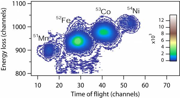
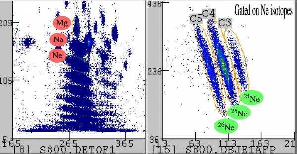
The following figures depict some of the S800 SpecTcl spectra used for the tunning of the S800.
Energy loss in the ion chamber vs. time of flight measured between the object scintillator and the E1 scintillator (trigger) at the end of the focal plane
(In)elastic scattering of the incoming "cocktail beam" on a 256 mg/cm<sup>2</sup> Au target (spectrograph in focus mode)
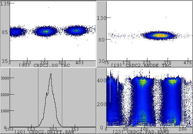
Upper left: Three 124Sn charge states in the CRDC2 x-y spectrum
Upper right: Amplitude of the CRDC2 anode signal vs. drift time (this is a diagnostics spectrum showing that the response of the CRDC is not correlated with the y position).
Lower left: Raw drift time measured in CRDC2
Lower right: Charge distribution induced in the pads by the three 124Sn charge states hitting CRDC2.


