This is an old revision of the document!
Table of Contents
Vacuum control
General Information
Vacuum control and monitoring of the S800 is provided via NCS application PanelMate, through the S800vac file, in directory \\exp\files\control\ncsdata\General\Qt\Templates. (Analysis line vacuum control pages are also available in the A1900_Vacuum PanelMate.) The vacuum system is divided in consecutive sections separated by gate valves. Each page in S800vac corresponds to a different vacuum section:
- Page 1: Vacuum section 13 corresponds to the segment of the beam line that includes the object-box between ion gauges I177GV and I190GV. The ion-gauge monitoring the vacuum pressure in the object box is I188IG
- Page 2: Vacuum section 14 corresponds to the segment of the beam line that includes the upper-dipoles in the analysis line. It is defined between ion gauges I190GV and I212GV. The ion-gauge monitoring the vacuum pressure in this section is I203IG
- Page 3: Vacuum section 15 corresponds to the segment of the beam line that includes the intermediate-image chamber between ion gauges I212GV and I215GV. The ion-gauge monitoring the vacuum pressure in chamber is I213IG
- Page 4: Vacuum section 16 corresponds to the segment of the beam line that includes the lower-dipoles in the analysis line. It is defined between ion gauges I215GV and I246GV. The ion-gauge monitoring the vacuum pressure in this section is I225IG
- Page 5: Vacuum section 17 corresponds to the segment of the beam line that includes the target chamber. It is defined between ion gauges I246GV and I255GV. The ion-gauge monitoring the vacuum pressure in this section is I252IG
- Page 6: Vacuum section 18 corresponds to the segment of the beam line that includes the spectrograph magnets. It is defined between ion gauges I255GV and I265GV. The ion-gauge monitoring the vacuum pressure in this section is I267IG
- Page 7: Vacuum section 19 corresponds to the focal-plane chamber. It is isolated from the rest of the beam line by gate valve I265GV. The ion-gauge monitoring the vacuum pressure in this section is I264IG
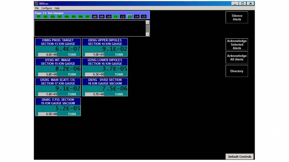
- Page 13: This page displays the pressures read by ALL the ion gauges of the analysis line and spectrograph (see figure below)
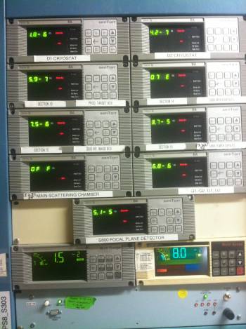
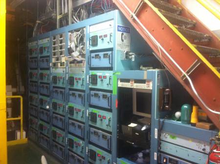
The readout from the ion gauges in the S3 vault is available through the control system, but these gauges cannot be turned on and off remotely. They are switched on and off locally by pressing the EMIS button on their controllers, which are located in the S3 vault on the middle level in the electronics racks under the stairs to the top level (see figures below). An ion gauge must be turned off by entering the vault before its beamline section can be vented.
All vacuum sections in the in the S800 have automated control of venting and pumpdown that operates valves and pumps (but not ion gauges) in the right sequence with the appropriate delays. In beamline section containing detectors, this automated control must be coordinated appropriately with steps to protect detectors.
Object Box
The ion gauge for the Object station chamber vacuum system makes too much light for the object scintillator. This ion gauge I188IG should be left off except when actually monitoring the vacuum level.
As stated above (see figure above), this ion-gauge can only be turned off “locally” by pressing the EMIS button on its controllers, which are located in the S3 vault on the middle level in the electronics racks under the stairs to the top level.
Target Chamber
The venting and pumping of the target area vacuum chamber is taken care of by the experimenters. Since this chamber is always shifting between different configurations, the status of the system as displayed on the PanelMate control page may not be reliable at any given time. The readout from the ion gauge should be fed into the PanelMate for either configuration. The state display and the ability to control the two beamline gatevalves, I246GV and I255GV, should also be functioning in PanelMate for either configuration, but the interlock status display and the interlock functionality to protect from opening either gatevalve at the wrong time may not be set up correctly.
Important note: Ensure that the experimenters never pump the chamber down if the spectrograph vacuum section is vented. The pressure gradient between both sections would “push” the structure of the spectrograph beam line towards the target chamber, potentially damaging the bellows of the line.
Venting analysis-line lower-dipole section
In order to ensure that the beamline in the target area is properly aligned with respect to the beam axis, it is necessary to install a telescope in between the last two quadrupoles of the analysis line, as well as a “cross hair” plate in between the last quadrupole and the target chamber. Although the alignment of the telescope is done by lab staff (e.g. Dave Sanderson), the user is responsible for removing the gate valve I246GV separating the analysis line and the target area. This of course, requires that the lower-dipole section is properly vented. The venting process is generally done by the device physicist, following the steps:
- Verify that the target area is vented.
- Using the EMIS controllers in the middle level of the S3 vault (see figure above), ensure that the ion gauge I225IG is turned off.
- Ensure that gate valves I246GV (between lower-dipole section and target area) and I215GV (between intermediate image area and the lower-dipole section) are closed.
- Open S800vac with PanelMate.
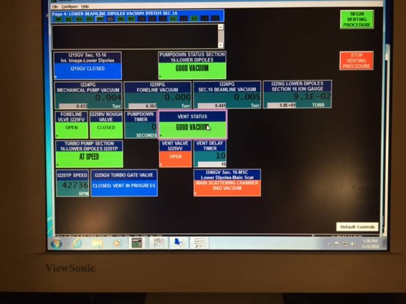
- Go to page 4 (“lower beamline dipoles vacuum system, section 16”)
- Window “VENT STATUS” should be green and display “GOOD VACUUM”
- Click on “VENT STATUS” and select “BEGIN VENTING PROCESS”. The I225GV turbo gate valve will be automatically closed (see figure below). However, the venting process won't be complete until you open the manual valve.
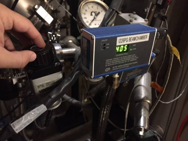
- Walk to the bottom level of the S3 vault, near the intermediate image box. Locate the I226PG Pirani gauge and ensure that it reads rough-vacuum pressure (few militorr).
- Slowly open the manual valve (see picture below) and verify that the pressure read in I226PG raises slowly.
- After the section is vented (atmospheric pressure) close the manual gate valve.
Spectrograph
This system is pumped with cryopumps. Please do not vent this section if the target chamber is under vacuum pressure. The pressure gradient between both sections would “push” the structure of the spectrograph beam line towards the target chamber, potentially damaging the bellows of the line.
Focal Plane Box
Venting, pumping, and opening the Focal Plane Box vacuum system involves too many details required for the protection of critical detectors for it to make sense to distribute these tasks to more than a few people. Ability to carry out these tasks is anyway not needed for routine operation of the S800 for experiments. Thus, these jobs will be reserved for the device owner and the detector lab. This section describes the more general information about this vacuum section that is needed to be an informed user of the system.
If this vacuum chamber is isolated from the rest of the beamline by I246GV being closed, the typical operating vacuum in this chamber is below 5e-5 Torr either with the gas detectors filled or with their bypass valves open to the chamber. With I246GV open, the vacuum should improve because of the better pumping capacity within the spectrograph.
The ion gauge providing pressure information to the control system is the one located on the top of the vacuum chamber just after the last dipole. The nearby ion gauge on the north side of the vacuum assembly is used for the vacuum-based interlock to protect the PMTs for the Focal Plane scintillator.

