User Tools
Sidebar
BAM Group
THAT'S RIGHT
B A M
DAY 1:
2. We are using the St. George recoil separator to study the reactions: 22Ne(α,γ)26Mg,
22Ne(α,n)25Mg
3.
b. The (x|x) term is the magnification of the x-position. The (x|a) term is the focusing factor for angle a. (a|a) is the magnification of the a angle. The (a|x) term is the focusing factor for position x.
c. An increase in the energy leads to a decrease in the amount of bending due to the dipole magnet and vice versa. Here you can see two rays with +/- 5% change in energy.
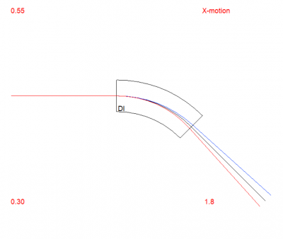 The blue ray has the increase in energy while the red ray has the decrease.
Remember to take the transpose of the transport matrix given by COSY to extract matrix elements correctly.
DAY 2:
4. For the (α,n) channel, the important beam energy in inverse kinematics is ~3.8 MeV beam of 22Ne. The corresponding max recoil angle is ~35mrad, and the recoil energy spread is ~ 7.3%. A plot of the recoil
angle and energy spread as a function of beam energy:
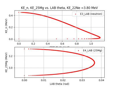
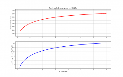
This reaction is very difficult - it barely fits in St. George, and the predicted cross section is incredibly small for the neutron channel. The threshold for the neutron channel corresponds to a beam energy of 3.12 MeV.
5. The most recent measurement of the neutron channel is given in this paper: Jaeger et al.
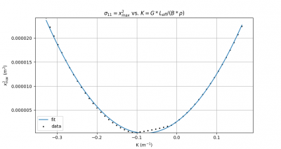
6. Modifying the emittance script to (file:emittance_script_auto_loop.rar), it loops through the Quad field tip strength around the minima and saves VMAX(RAY(1)) to a file.
The provided slides define K as the inverse of the focal length of the 'thin lens'. For a quadrupole, K = 1/f = G*L_eff/(B*rho). After this conversion, plotting this data and fitting results in:
Model: P1*x^2 + P2*x + P3
P1 = 3.82e-04+/-2.03e-06 m^2
P2 = 6.05e-05+/-4.22e-07 m^3
P3 = 2.59e-06+/-5.20e-08 m^2
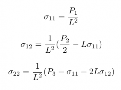
This, with the length to the quad center L=6.08505m, leads to an emittance of e = 0.237 mm*mrad. This is fairly close to the defined rays, which have an emittance of e = 1mm*0.2mrad = 0.2 mm*mrad.
DAY 3:
7. We are using COSY file for St. George.
https://wikihost.nscl.msu.edu/JIOSS/doku.php?id=st._george_cosy_model
Run St. George with normal settings, find mass resolution of 59.26
To print mass resolution, use command
WRITE 6 'Mres = '&S(MRES);
Now vary effective length of Q3 by factor 1.03:
- defined in {section 2} as MQ LQ3+DLQ3 Q3*QF RQ3;
Change to:
MQ 1.03*(LQ3+DLQ3) Q3*QF RQ3;
MQ <length> <flux density at pole tip> <aperture>
Also need to reduce drift lengths either side of quadrupole so that position of center of quadrupole does not change.
Change drift before Q3 definition from
DL DL6-0.5*DLQ3;
to
DL DL6-0.5*DLQ3-0.03*(LQ3+DLQ3)/2;
Change drift after Q3 definition from
DL DL7-0.5*DLQ3-0.5*DLQ4;
to
DL DL7-0.5*DLQ3-0.5*DLQ4-.03*(LQ3+DLQ3)/2;
New mass resolution after making this change is 38.1
Improved method for changing effective length of Q3:
Line 545, we have definition DLQ3 := 0.353 - LQ3
(This is the difference between measured effective field length and defined effective field length, LQ3)
Now we just need to change the measured effective length by PMOD*0.353 where PMOD is a variable for % modification, e.g. PMOD = 1.03
Definition of MQ already includes factor DLQ3: MQ LQ3+DLQ3 Q3*QF RQ3;
as do the drifts before and after:DL DL6-0.5*DLQ3; and DL DL7-0.5*DLQ3-0.5*DLQ4;
Attempt to recover best mass resolution:
To do this we will try to fit the strength of Q3. Doing this calculation to 5th order, we are able to recover the initial mass resolution of 59 with a Q3 quad strength of .88 which is a 2% decrease in the quad strength.
DAY 4:
Today we are working on problem 8. We are using the command SA <DX> <DY> to change the beam position. SA <DX> <DY> offsets the optics axis x by DX and y by DY. To 5th order, changing the x offset by .5 mm leads to a 5% change in the mass resolution. Any amount of change of the y offset leads to no change in the mass resolution. This is pretty weird…
We changed the beam size by changing the values of variables X and Y. Increasing X by .1 mm caused the mass resolution to decrease by 5%. Increasing Y by the same amount leads to no change in the mass resolution…
By adding 2 mm to the lengths of quad 3 and 4 and decreasing the drift lengths after them by 2 mm, we reach a 5% change in the mass resolution. We can shift optical elements in the x-y plane by placing the SA command before and after the element you are shifting. For instance, if you want to shift a quadrupole in the positive y-direction by 5 mm, you would use the following command:
SA 0 .005;
MQ LQ3+DLQ3 Q3*QF RQ3;
SA 0 -.005;
We used this command to shift quadrupole 3 up by 5 mm which changed the mass resolution by 5%. Shifting the quadrupole by 0.5 mm in the x-direction changes the mass resolution by 5%.
We can use the TA command to rotate the quad about the x and y axes. This has the same syntax as SA. Rotating about the x-axis by .05° changes the mass resolution by 5%. Rotating about the y-axis by .15° changes the mass resolution by 5%.
To determine how much roll is allowed before changing the mass resolution by 5%, we use the RA command which takes one angle and rotates about the z-axis. An angle 0f 2.3° is allowed.

