User Tools
Sidebar
Team Alpha Gamma
Group Project:
1) St George
2) 14N(a,g)18F
3) Dispersion achieved by adjusting the PD variable (i.e. creating an energy spread from the central ray). An envelope of rays is used to visualize the dispersion, ER 1 3 1 1 1 3 1 1 ;.
The first column of the matrix outputted by COSY corresponds to the first row of the transfer matrix that was covered during the lectures. (final)=(transfer matrix)(initial) r_11 = magnification, r_12 = focus, r_16 = dispersion
The dispersion is given by DE/E*(x|dK). (x|dK) is the R_16 element of the transfer matrix resulting from the COSY calculation. For a 14N3+ beam at 14MeV, (x|dK)=0.229, the dispersion is calculated as x = (dK/K)(x|dK).
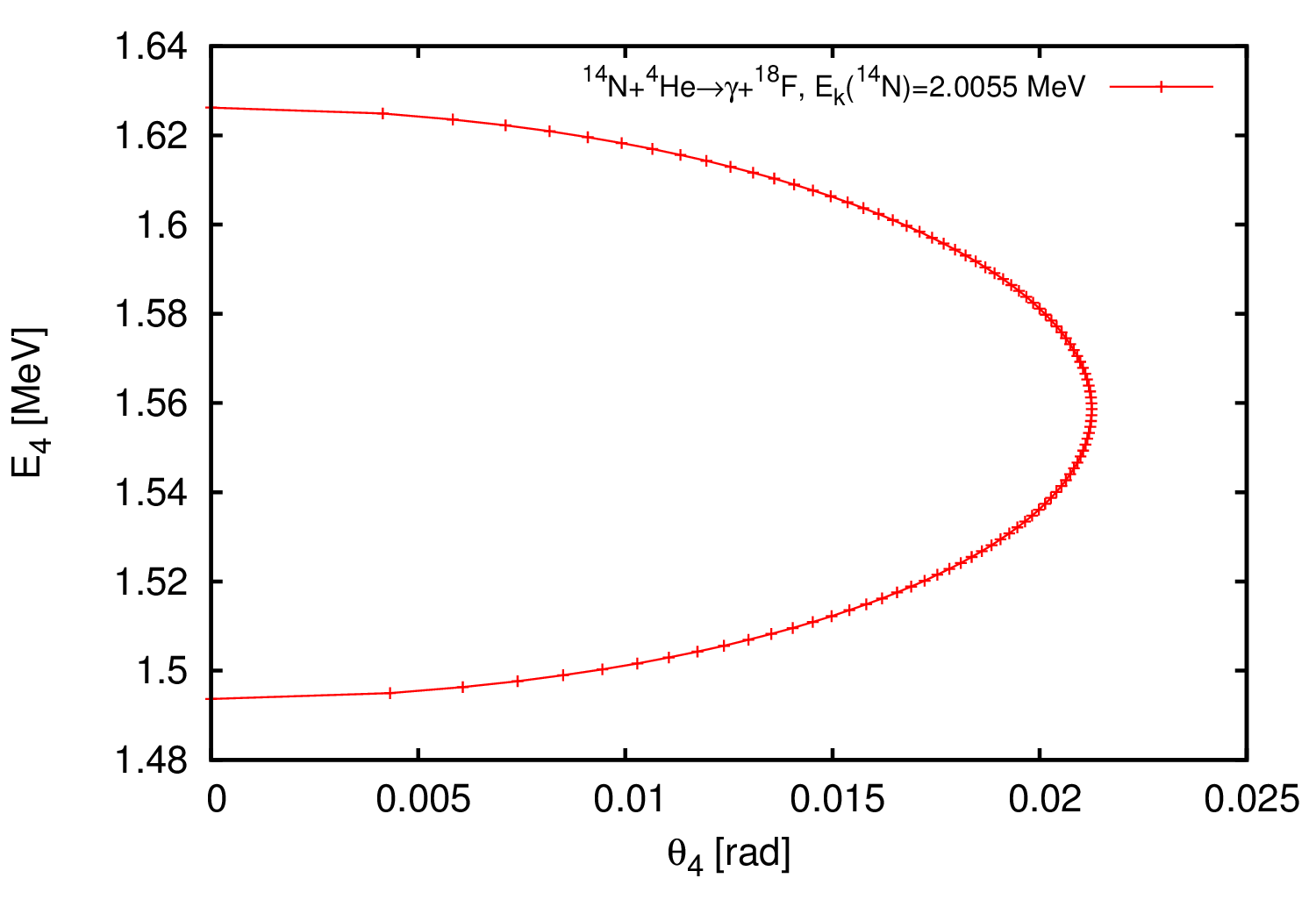
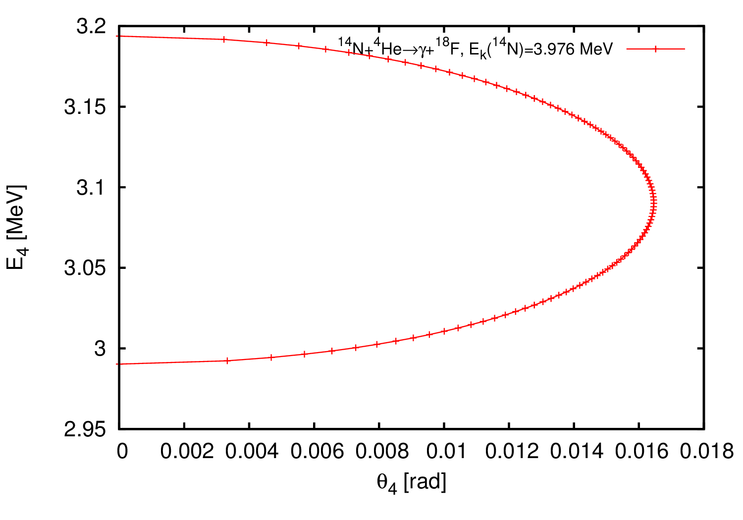
4) The reaction 14N(a,g)18F is chosen. Resonances reported as alpha-energies at 573 keV and 1.136 keV, which correspond to center of mass energies of 445.7 keV and 883.6 keV respectively (E_cm = m_target/(m_beam+m_target)*E_lab. Inverse kinematics are used, so 14N beam energies of 2005.5 keV and 3976.0 keV are needed.
The energy acceptance of St. George is dE/E = +/- 7.4%, and the angular acceptance of St. George is theta_max = 40 mrad. For the 445.7 keV resonance, DE/E = (1.63-1.559)/1.559 = 0.04338 (4.338%), the maximum theta is 21.26 mrad, both of which are within the limits of St George. For the 883 keV resonance, DE/E = (3.1937-3.08796)/3.08796 = 0.0342 (3.42%), the maximum theta is 16.46 mrad, both of which are within the limits of St George.
Problem 5
Information about the 14N(a,g)18F reaction can be found in Phys. Rev. C 62, 055801 (2000).
Problem 6
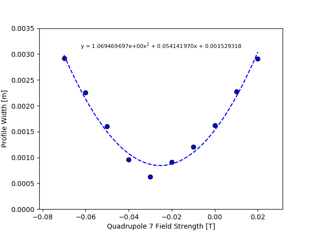
The quadrupole strength of Q7 was was varied by changing line 117 of emittance_script.fox. This line looks like MQ 0.3401 0.02 0.13 ; {============⇒}{Q7}. As explained in a comment at the bottom of emittance_script.fox, the profile width can be obtained with VMAX(RAY(1)). Therefore, at the end of {Section 2}, the following line was added: WRITE 6 'VMAX: ' VMAX(RAY(1));. The following data was collected.
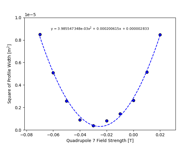
The above fit with a second order polynomial was not satisfactory. Instead, the profile widths were squared, which led to a satisfactory fit:
The distance L from the center of quadrupole Q7 to the focal plane FP2 in emittance_script.fox was extracted by adding half of the length of Q7 to all the drift lengths after Q7: [(0.3401)/2] + [0.5 + 2.365 + 0.50 + 0.26 + 0.28 + 0.26 + 1.75] = 6.08505 m.
As shown on the plot, the coefficients from the above fit are a = 3.98554735e-03, b = 2.00614706e-04, and c = 2.83331538e-06.
According to page 2 of emittance_trans_v2.pdf, the emittance can be calculated from the fit as
emittance = epsilon = sqrt(a*c)/L^2 = sqrt(3.98554735e-03 * 2.83331538e-06)/(6.08505)^2 = 2.86987e-06.
There is currently a lot of debate and confusion in the summer school as to whether this calculation is correct.
Problem 7
Running stgeorge.fox without any modifications yields the following mass resolutions (the first value printed to the terminal is the x-component of the mass resolution, and the second value printed to the terminal is the y-component of the mass resolution):
Mres_x = 60.123, and
Mres_y = 59.262.
The effective field length of Q2 in St. George was changed by 3%. At the same time, the surrounding drift lengths were changed to make sure the position of the center of Q2 did not change. All of this was achieved by modifying the {ACTUAL RECOIL SEPARATOR DESCRIPTION} section of stgeorge.fox. The line for quadrupole Q2 was changed from MQ LQ2+DLQ2 Q2*QF RQ2 ; to 1.03*(LQ2+DLQ2) Q2*QF RQ2 ;.
The drift length before Q2 was changed from
DL DL2-0.5*DLQ1-0.5*DLQ2; to
DL DL2-0.5*DLQ1-0.5*DLQ2-0.015*(LQ2+DLQ2);.
The drift length after Q2 was changed from
DL DL3-0.5*DLQ2; to
DL DL3-0.5*DLQ2-0.015*(LQ2+DLQ2);.
Note that the drift lengths were changed by (3%)/2 = (0.03)/2 = 0.015 to be symmetric.
With these modifications, the mass resolution has decreased to Mres_x = 19.541, and Mres_y = 19.438.
The mass resolution is calculated in MASS SEPARATION PROCEDURE as MRES:=ABS(ME(1,7))/(RECOILSIZE+BEAMSIZE);. Note that ME is a built-in cosy command for getting the momentary value of a matrix element. The parameters for ME are explained in Sec. 3.2.1 of the cosy manual. In ME(1,7), the 1 refers to x and the 7 refers to dK.
Because we increased the effective field length of Q2, a natural choice would be to decrease the field strength of Q2 in order to recover the original mass resolution. This is because then the field integral would be the same as before. A fitting routine was added to stgeorge.fox in an attempt to recover the best mass resolution.
Near the end of stgeorge.fox, the lines
BP;RECOIL_LINE;WRITE 6 'Mres = '&S(MRES);EP;PP -12 0. 0.;
were commented out and replaced with
FIT Q2 ;UM ; CR ;RECOIL_LINE;OBJ := 1/ABS(MRES);WRITE 6 'Fit Q2: ' Q2 'OBJECTIVE: ' OBJ '1/OBJ: ' 1/OBJ;ENDFIT 1E-5 1000 1 OBJ ;
After converging, the fitted value of Q2 is 0.1778619910379541. The original value of Q2 was 0.1828815622086947 (from section {Field for the standard particle … scaled by QF to adapt field to right p/q}).
This is a (0.1828815622086947 - 0.1778619910379541) / (0.1828815622086947) * 100 = 2.74% decrease. This almost compensates for the 3% increase in the effective field length.
Problem 8
As stated in Problem 7, the mass resolutions of stgeorge.fox without any modifications are
Mres_x = 60.123, and
Mres_y = 59.262.
We adjusted beam parameters until we saw Mres_x and Mres_y drop to around 55.
The beam position (offsetting the optical axis) can be changed with the SA command.
With SA 0.0005 0.0;, Mres_x = 55.18793673041390 and Mres_y = 54.57598045160019. This is close to a 5% decrease.
With SA 0.0 0.0014;, Mres_x = 55.03721889327960 and Mres_y = 54.24635345218690. This is close to a 5% decrease.
The beam size can be changed by adjusting the first and fourth parameter of the SB command to change the x- and y-extent respectively.
With these two parameters each changed from the default 0.0015 to 0.0017, Mres_x and Mres_y each drop to about 55. A 0.2mm increase in size measurably drops the mass resolution.
Decreasing these parameters only increases the mass resolution. It seems the smaller the beam spot, the larger the mass resolution.
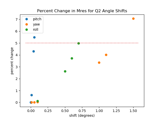
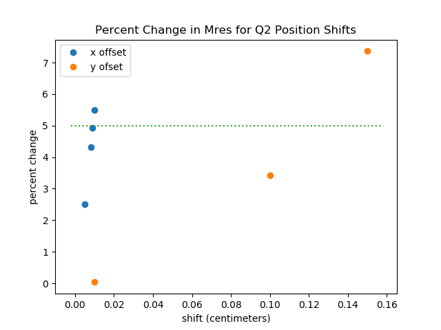
b) Adjusting the pitch, roll, yaw, x-position, and y-position of Q2 caused a drop in mass resolution at the mass slits (FP2), right after the Wien filter. In COSY, “TA” is used to adjust the pitch and yaw, “RA” to adjust the roll, and “SA” to adjust x and y position. Since the shifts are made relative to the central ray, they must be “undone” directly after the quadruple to prevent the shift form effecting the downstream elements. The below plots show the relative effects on M_res. For Q2 the mass resolution is more sensitive to changes in pitch and x-offset.

