This is an old revision of the document!
Table of Contents
During experiment
This section describes support tasks that are typically requested from experimenters.
Mask calibration
CRDC mask calibrations are used to relate channel numbers and true physical distances in mm for the position-sensitive cathode readout drift chambers. A mask with a distinct and well-determined pattern of slits and holes can be inserted remotely in front each CRDC. The particles passing through the holes leave the pattern of the mask in the position spectrum of the detectors. First-order polynomials are used for the calibration. In x direction, where the position is determined from the charge induced in the pads, the slope of the first-order polynomial is fixed by the geometry of the detector to 2.54 mm/pad. The offset has to be set to center the “beam hole” at 0 mm. Since the drift time depends on the drift voltage, the gas composition and pressure, the y slope will change from experiment to experiment.
Note:
- Unreacted beam does not provide good conditions for performing the mask calibration, but sometimes it provides the only option
- To cover mask
- Detune non-dispersive y quad (ratio=0.5) in spectrograph to spread beam in y
- Sweep beam across dispersive direction using spectrograph dipole
How to take data for the mask calibration:
- Set the trigger to S800 singles and downscale factor 1
- On PanelMate, open page 4 in S800DRIV
- Click on “upstream mask” and hit the “insert” button. This puts the mask in front of CRDC1
- Start a run without taking to disk and look in the S800 SpecTcl at the 2D xy position spectrum of (s800.fp.crdc1.x,s800.fp.crdc1.tac). If it starts to look like the spectrum shown below (the screenshot corresponds to mask 2, mask 1 looks inverted, in the sense of the triangle of dots pointing downwards), start taking data to disk until it has about the quality of the screenshot shown. If only a small fraction of the S800 focal plane is illuminated (dispersion-matched optics), consult with the S800 group to sweep the beam across the focal plane by changing the Brho of segment 8. The figure below shows the SpecTcl spectrum of the mask “shadow” measured in CRDC2 during a reaction setting.
- Remove the “upstream mask” with PanelMate
- Repeat the procedure with CRDC2 by inserting the “downstream mask” on the same PanelMate page.
Particle identification corrections
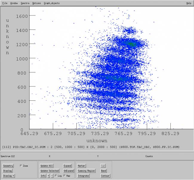
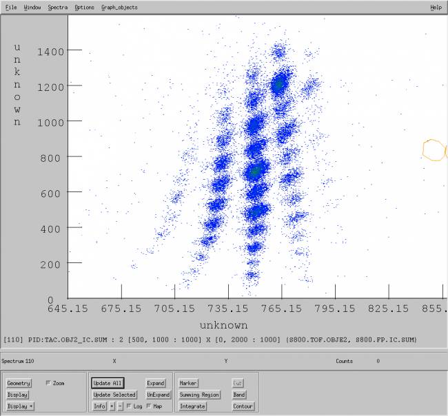
In a typical reaction setting, the dependences of ToF on the dispersive angle and position make it hard to resolve the particle-identification spectrum. As an example, the figure below shows the PID SpecTcl spectrum PID:TAC.OBJ_IC.SUM using the OBJ-FP ToF from the ORTEC TAC:
The following process describes how to improve the PID resolution. This correction is supposed to be done “offline”, i.e. using a data file recorded in the stagearea:
- The SpecTcl parameter s800.tof.obje2 corresponds to the “raw” parameter s800.tof.tac_obj, corrected from the dependences described above
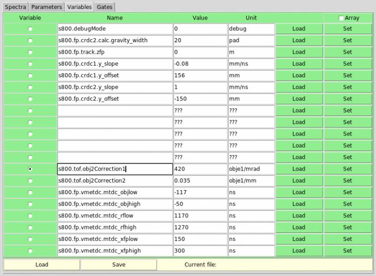
- Open the Variables page in SpecTcl and make sure that the variables s800.tof.obje1Correction and s800.tof.obje2Correction are zero. (The figure below shows the Variables page with the final values of the correction variables)
- In SpecTcl GUI, click Attach to File and select data file run-xxxx-xx.evt in directory /user/s800/stagearea/experiment/runxxxx, where xxxx stands for the run number
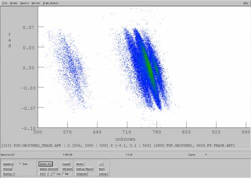
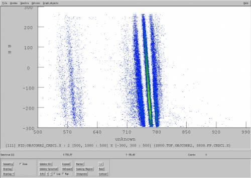
- Looking at the spectrum PID:TAC.OBJ2_TRACK.AFP (figure below, left), change the value of the variable s800.tof.obje1Correction
- Enter a new value (typically in the range 500-1000)
- Click Set
- Re-scan the data file
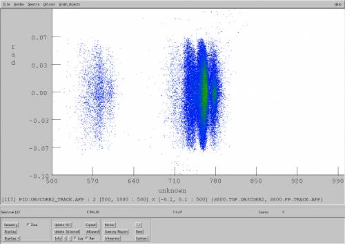
- Keep trying different values, until the dependence is eliminated. The figure below (right) shows the corrected spectrum (for this particular case, s800.tof.obje1Correction = 450)
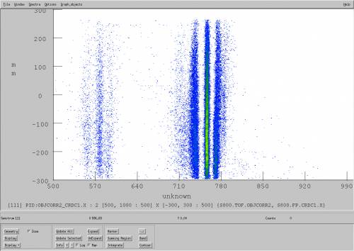
- Repeat the process looking now at the spectrum PID:TAC.OBJ2_CRDC1.X (figure below, left)
- Enter a new value for the variable s800.tof.obje2Correction (typically in the range 0.01-0.1)
- Click Set
- Re-scan the data file
- Keep trying different values, until the dependence is eliminated. The figure below (right) shows the corrected spectrum (for this particular case, s800.tof.obje2Correction = 0.05)
- The figure below shows the spectrum PID:TAC.OBJ2_IC_SUM after the right corrections were included in SpecTcl
- The correction process described above can be used for other ToF. SpecTcl includes a set of corrected ToF parameters:
- s800.tof.obje2: Corrected ToF calculated from the OBJ-FP TAC
- s800.tof.xfpe2: Corrected ToF calculated from the XFP-FP TAC
- s800.tof.obje1: Corrected ToF calculated from the OBJ-FP Phillips TDC
- s800.tof.xfpe1: Corrected ToF calculated from the XFP-FP Phillips TDC
- Note that although the SpecTcl correction variables are shared between the ToFs from the TACs and Phillips TDC, they won't work simultaneously, i.e. the variables that work to “clean” the TAC-based PID spectrum won't work for the TDC-based PID spectrum
Handling detectors
Shimming OBJ scintillator
Shimming of the OBJ scintillator (or replacement) is required when the efficiency (measured by the experimenters) drops to about 85%. Please, refer to the operations guideline describing the procedure.


