This is an old revision of the document!
Table of Contents
Detector gas handling system
General Information for focal-plane gas handling system
The gas handling systems for both Focal Plane gas-filled detectors – the Ionization Chamber and the CRDCs – are remotely controlled via a single LabView application running on the computer S800FP-PC in the S3 vault. This computer can be accessed remotely from the desktop of computer u6pc5, by clicking in the icon S800 Vault PC, or by typing xfreerdp /u:s800 /v:35.9.56.104 from a Linux terminal. A terminal will pop-up asking for the s800 password. Once the virtual session in S800FP-PC is open, the gas handling system can be opened by clicking in the corresponding icon on the desktop FPGHS_TCPIP-II. This icon opens the local directory C:/Users/s800/Desktop/FPGHS_TCPIP-II. Once there, run the Labview executable FPGHS_TCPIP-II.exe.
Note that since the same roughing pump drives the gas handling systems for both gas-filled detectors, extra precautions must be taken to protect one detector from the pressure of the other detector. The fact that the same pump drives both systems is not indicated on the graphics for the LabView control application
Required controls and monitoring
- LabView gas handling system application FPGHS_TCPIP-II.vi
- PanelMate S800vac.ui page 07: Focal Plane Detector
LabView Control Program for focal plane detectors
To start the gas handling system control application, click on the LabView icon FPGHS_TCPIP_Corrected_V01 on the S800FP-PC desktop.
- A log file should be specified before operating the gas handling system
- A window automatically pops up asking for the name of the log file when the program starts
- Use the number of the current experiment (or “test”) as the name of the log file and save in file /intranet/files/departments/operations/s800/TO_BE_SPECIFIED
- The On indicator next to Is VI running? will flash until a log file is specified and the program initiates communications with the hardware
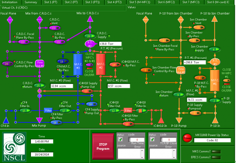
- Click the Valves tab at the top of the LabView window to display the overview of the gas handling system (see Figure below)
- The triangles on the valve control buttons (as well as the square valve status indicators near the control buttons) are red to indicate that a valve is closed (e.g., control 25 for the CRDC return above) and green to indicate a valve is open (e.g., control 22 for the CRDC bypass above)
- The gas handling control application should always remain open during the entire time either detector is filled with gas to ensure the log file is continuously updated
- Once both detectors are empty, this application can be closed with the “X” button on the upper right corner of the window.
Preparation of Gas bottles for filling of focal-plane detectors
In Data-U6
- Ensure I265GV is closed (in PanelMate S800vac.ui page 07) to isolate focal plane vacuum chamber from the rest of the beamline
- Confirm that the focal plane chamber is under vacuum
- Confirm that the only open gas handling system valves are 4, 5, 6, 7, 20, 21, 22 and 23
- (Check section on vacuum control for further details.)
In the S3 vault
- Ensure that the gas handling system roughing pump is running and has a good vacuum
- The pump sits on the floor under the focal plane behind the south support post
- The display unit for the pressure at the pump has a needle indicator and is mounted under the focal plane on the south support post
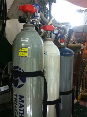
- Ensure that the main valves on the gas bottles are open (see pictures below)
- Open valves downstream of regulators in each bottle
- Ensure that the gas bottles are not empty
- The gas regulators are not normally adjusted. They should all be set to provide a pressure around 20 psi
- The bottle supplying the P-10 gas for the ionization chamber is secured to the cross-brace of the south support for the focal plane chamber. It has an electronic Ashcroft pressure gauge upstream of the regulator (toggle on and off with the “on/off” switch) and a mechanical pressure gauge downstream of the regulator
- The bottle supplying CF4 (tetrafluoromethane) gas for the CRDCs is secured to the cross-brace of the south support for the focal plane chamber. It has an electronic Ashcroft pressure gauge upstream of the regulator (toggle on and off with the “on/off” switch) and a mechanical pressure gauge downstream of the regulator
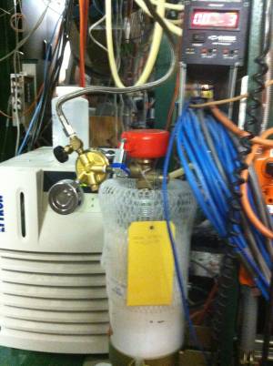
- The bottle supplying isobutane (C4H10) for the CRDCs is secured to the south support post for the focal plane chamber. It sits on a scale for monitoring the isobutane consumption – the electronic display for the scale sits on the chiller unit under the focal plane chamber. It has a mechanical pressure gauge downstream of the regulator
Filling Ion Chamber with Gas
- Follow instructions under Preparation of Gas bottles
- Monitor the pressure of the focal plane vacuum chamber (as read out via the I264IG ion gauge in PanelMate S800vac.ui page 07) while detectors are being filled with gas; the pressure normally stays below 5E-5 Torr.
- Confirm that the detector pressure as indicated by the display labeled P.T. #1 reads below a couple of Torr
- To zero this display:
- Click on the Slot 3 (PT1) tab to access the details page for PT #1
- Click the Zero Sensor button
- Click the Valves tab at the top of the LabView window to return to the overview display of the gas handling system
- Close valves 6 and 7
- Open valve 2; the flow reading at MFC #1 should jump momentarily
- Fill Ion chamber
- Enter the desired fill pressure and start the automatic filling process
- Click on the tab labeled Slot 8 (M-card) IC to access the page with the pressure set point control
- Enter the desired pressure (typically 300 Torr) in the field under the knob labeled Set Point
- Click button labeled Update Set Point
- Click button labeled Return to AUTO Mode on left to start filling/regulation
- Click the Valves tab at the top of the LabView window to return to the overview display of the gas handling system to monitor filling. The flow readings for MFC #1 will increase and eventually disappear as the readout value overflows the display field (this is normal behavior)
- Open valve 9
- If necessary, the filling process can be stopped at any time by pressing the valve button labeled Close MFC #1
- The filling process will take several minutes
- When the detector is filled, close valve 5
Filling CRDC1 and CRDC2 with Gas
- Follow instructions under Preparation of Gas bottles
- Monitor the pressure of the focal plane vacuum chamber (as read out via the I264IG ion gauge in PanelMate S800vac.MT2 page 07) while detectors are being filled with gas; the pressure normally stays below 5 x 10⁻⁵ Torr.
- Confirm that the detector pressure as indicated by the display labeled P.T. #2 reads below a couple of Torr
- To zero this display:
- Click on the Slot 4 (PT2) tab to access the details page for PT #2
- Click the Zero Sensor button
- Click the Valves tab at the top of the LabView window to return to the overview display of the gas handling system
- Close valves 22 and 23
- Open valves 10 and 15
- Open valve 12; the flow reading at MFC #2 should jump momentarily
- Open valve 17; the flow reading at MFC #3 should jump momentarily
- Fill CRDCs
- Enter the desired fill pressure and start the automatic filling process
- Click on the tab labeled Virtual Ch. 0 (CRDC) to access the page with the pressure set point control
- Enter the desired pressure (typically 40 Torr) in the field under the knob labeled Set Point
- Click button labeled Update Set Point
- Click button labeled Return to AUTO Mode on left to start filling/regulation
- Click the Valves tab at the top of the LabView window to return to the overview display of the gas handling system to monitor filling. The flow readings for MFC #2 and MFC #3 will increase. The LabView application controls the gas mixing ratio based on the flow ratio (scaled with a calibration constant)
- Open valve 25
- If necessary, the filling process can be stopped at any time by pressing the valve button labeled Close MFCs #2 & #3
- The filling process will take several minutes
- When the detector is filled, close valve 21
Removing Gas from Focal Plane Detectors
- Monitor the pressure of the focal plane vacuum chamber (as read out via the I264IG ion gauge in PanelMate S800vac.MT2 page 07) while gas is being removed from detectors; the pressure normally stays below 5E-5 Torr
- Ensure that the system is in the normal state for flowing gas through the detectors
- Confirm that the focal plane chamber is under vacuum
- Confirm that the only open gas handling system valves are 2, 4, and 9 for the Ion Chamber and 10, 12, 15, 17, 20, and 25 for the CRDCs
- Confirm that the detector pressures as indicated by the displays labeled P.T. #1 for the Ion Chamber and P.T. #2 for the CRDCs show the correct fill values (typically 300 Torr and 40 Torr, respectively)
- Ensure that I265GV is closed to isolate focal plane vacuum chamber from spectrograph
- Stop the gas flow into both detectors by clicking valve buttons labeled Close MFC #1 and Close MFCs #2 & #3
- Isolate the gas supply by closing valves 2, 12, 17, 10, and 15
- Open valves 5 and 21
- IMPORTANT: Before opening valve 8 (next step), CLOSE VALVE 25 to protect CRDCs from Ion Chamber pressure
- Empty Ion Chamber to a pressure at or below the pressure of the CRDCs
- Open valve 8
- Wait for the Ion Chamber pressure to reach or drop below the pressure in the CRDCs; this process will take several minutes
- Finish emptying both detectors
- Open valve 25
- Open valve 24
- Wait for the pressure in both detectors as indicated by the displays labeled P.T. #1 and P.T. #2 to reach 0.5 Torr or less; this process will take at least an hour
- Close valves 9 and 25
- Close valves 8 and 24
- Open valves 6, 7, 22 and 23
- Enter S3 vault and close valves downstream of regulators in gas bottles: P-10 and CF4 (tetrafluoromethane). Close the main valve for the C4H10 bottle.
Tracking Gas bottles pressures
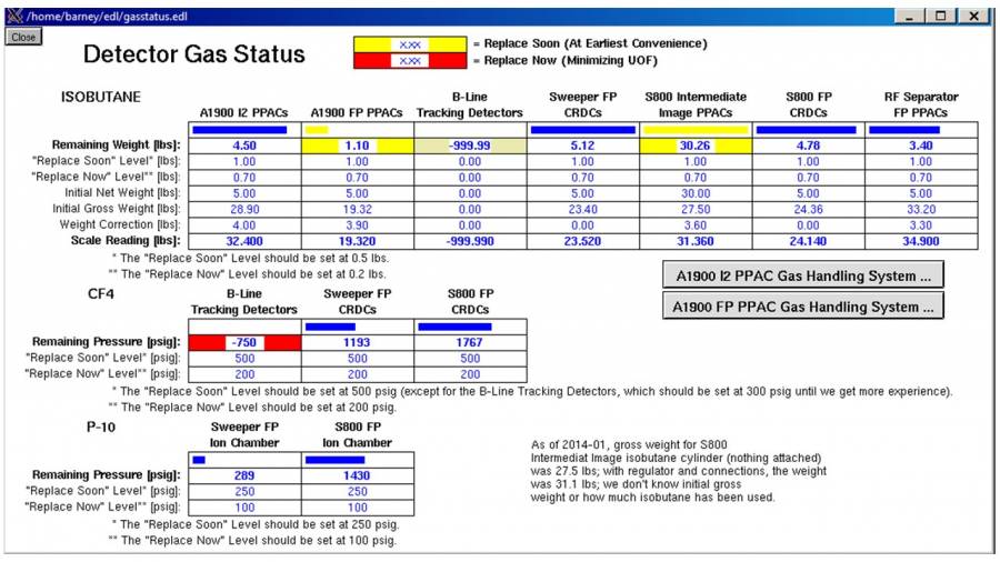
In order to track the status of the gas bottles for the ionization chamber, the CRDCs, and the TPPAC, it is possible to monitor their remaining pressures from Barney. Just open the A1900 page, then Tools, and then Gas Status. The following window will be displayed:
Replacing Gas bottles
In preparation


