This is an old revision of the document!
Table of Contents
S800 Tuning (XDT)
This page gives the steps that are followed when tuning the S800. The two possible tuning modes are included, namely, the Focus mode and the Dispersion-matching mode.
Before proceeding, it is mandatory to complete all the steps of the to-do list necessary to prepare the S800 for tuning. The preparation of the S800 for tuning is covered by the A1900 prior to every experiment.
Focus Mode
For most of the experiments in the S800, the analysis line is run in focus mode. In this optics, the analysis line is achromatic, i.e. the dispersive position of the beam focused in the target area (pivot point) does not depend on the momentum. Thus, this mode provides the biggest momentum acceptance (4%). On the other hand, since the spectrograph focal plane is chromatic, the resolution is limited to about 1 part in 1000 in energy.
Unreacted beam
In the first part of the XDT, the rigidity of the S800 is typically set to match the value of the fragment beam (selected in the A1900) after passing through the S800 target. This is where the term “unreacted beam” comes from.
Send beam to FP
- Ensure that the S800 spectrograph magnets are tuned to the right rigidity
- Verify that the beam blocker (labeled I255 Slits) in the S3 page of Barney is open:
- Expected “open” values for top and bottom slits are CT ~6.8 and CB ~3.2, respectively
- Ensure that CRAD04 (typically connected to object scintillator) is enabled with a rate limit of 20 kHz (CRAD04 looks at E1 up FP scintillator)
- Remember: S800 FP rate limit is 6 kHz
- Bias S800 FP scintillator photomultipliers
- Set bias to best guess based on previous experience for the fragment Z being used (bias will be adjusted later during tuning)
- Typical values from previous experiments:
- For He-3 @ ~130 MeV/u: UP (1790 V); DOWN (1760 V)
- For Be-12 @ ~30 MeV/u: UP (1770 V); DOWN (1700 V)
- For Ar-34 @ ~80 MeV/u: UP (1580 V); DOWN (1510 V)
- For Zn-58 @ ~44 MeV/u: UP (1400 V); DOWN (1340 V)
- For U-238 (88+) @ ~70 MeV/u: UP (1180 V); DOWN (1280 V)
- Have a good expectation of rate from A1900 group information or from timing scintillators (typically XF_SCI: extended focal-plane detector)
- Remove stops to look for beam at S800 FP with scalers and adjust beam rate with attenuators
- Look at FP scintillator scalers (E1 up, E1 down)
- There are typically a few scaler counts without beam
Object scintillator setup
- Bias detector. Typical bias: 1200-1800 V (up to 2200 V)
- Use scope to look at signal patched out to data U6 (channel #54 in data U6 patch panel)
- This signal is sent to the CANBERRA 454 Quad CFD in data U6
- One of the output from this CFD is sent (via patch panel #62) to the TAC and scaler (channel OBJ.Scint) in S3. The other output goes through a passive delayed, and is sent (via patch panel #67) to the Phillips TDC
- Check raising time and amplitude. Good signal: ~10 ns raising time; 400-500 mV amplitude
- Using the scope, check the CFD setting:
- Check CFD walk inspect signal in scope by triggering scope with CFD output
- Ensure that CFD delay cable is ok: about 80% of raising time of the input signal
- Adjust CFD threshold looking at scalers. The ratio of OBJ to XFP scaler rates (channels OBJ.Scint and XFP.Scint) should reflect the transmission of the cocktail beam
- Adjust MCFD threshold:
- Open configuration file MCFD16.tcl in /user/s800/operations/daq/usb/Configs
- The OBJ signal feeding this module is not patched out to data U6
- The OBJ signal from MCFD-16 module goes to the Mesytec MTDC32 module and scaler (channel OBJ.MCFD.Scint)
- Make sure that the threshold of the XFP MCFD channel is reasonable. Rates in scaler channels XFP.Scint and XFP.MCFD.Scint should be comparable
- Adjust MCFD OBJ threshold looking at scalers. The ratio of OBJ to XFP scaler rates (channels OBJ.MCFD.Scint and XFP.MCFD.Scint) should reflect the transmission of the cocktail beam
- Save new threshold in configuration file MCFD16.tcl
- Watch for no rate change on scaler display with a bias adjustment up or down of about 50-100 V
FP scintillator setup
- Set trigger to “s800 trigger”
- Ensure that the trigger GUI application is ready. Otherwise, open it by clicking button Launch ULM GUI in ReadoutGUI
- Under trigger tab select s800 trigger (which is E1 up by definition)
- Deselect experiment trigger
- SAVE TO FILE
- End and Begin ReadoutGUI to assert new trigger condition
- Select Spectcl window S800_SCINT.win
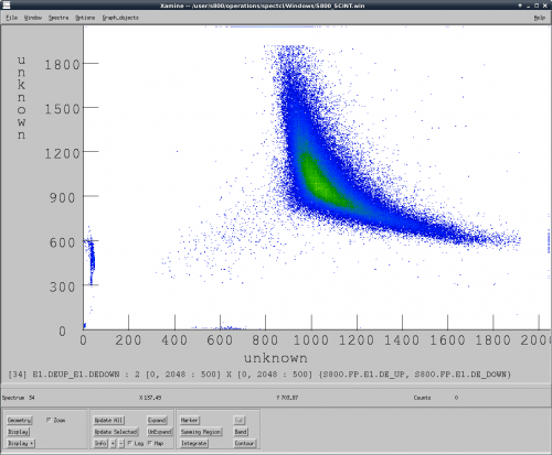
- Adjust bias looking at 2D spectra e1.deup_e1.dedown (showing the parameters s800.fp.e1.de_down vs. s800.fp.e1.de_up) for the FP E1 scintillator
- See spectrum below. Changing bias of this detector stretches the curve (i.e. shifts the blob in the middle of the curve corresponding to typical unreacted beam)
- Adjust biases so that unreacted beam are at 1/3 to 1/4 of dynamic range
- Reaction product will typically be similar enough to unreacted beam particles
- Different particles with different energy loss will shift the curve corresponding to particles covering whole FP
Ionization Chamber setup
- Gas should be flowing
- Bias detector
- Typical bias Anode: 200 V (should not draw current after bias is reached)
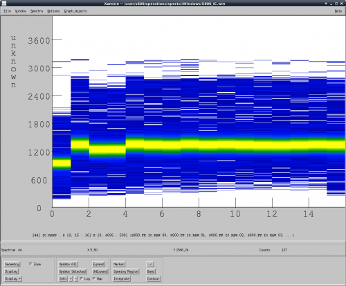
- Select Spectcl window S800_IC.win
- Adjust pad gains
- There are 16 pads each providing energy-loss information in the beam direction
- The idea is to make sure the dynamic range is OK so that heavy particles do not saturate the spectra; the pad gains do not have to be matched
- Use summary 2D spectra IC.raw (see spectrum below)
- Gains are controlled in s800shpini.tcl file in directory s800/operations/daq/usb/Configs (an example of the content of this file can be seen here).
- First shaper is for ion chamber
- Typically, only coarse gains are used
- End and Begin ReadoutGUI to assert new gain values
CRDCs setup
- Bias CRDCs
- Look at anode signal on scope while biasing drift and anode
- Patched to data-U6 on labeled connector
- 200 – 500 mV signals are good
- CRDC1 anode is noisier (digital noise) than CRDC2
- Bias CRDC1 and CRDC2. Typical starting values:
- For He-3 @ ~130 MeV/u: CRDC1 (Anode=1120 V, Drift=1000 V); CRDC2 (Anode=1120 V; Drift=1000 V)
- For Be-12 @ ~30 MeV/u: CRDC1 (Anode=970 V, Drift=1000 V); CRDC2 (Anode=970 V; Drift=1000 V)
- For Ar-34 @ ~80 MeV/u: CRDC1 (Anode=860 V, Drift=1000 V); CRDC2 (Anode=840 V; Drift=1000 V)
- For Zn-58 @ ~44 MeV/u: CRDC1 (Anode=740 V, Drift=1000 V); CRDC2 (Anode=740 V; Drift=1000 V)
- For Rb-74 @ ~40 MeV/u: CRDC1 (Anode=650 V, Drift=1000 V); CRDC2 (Anode=650 V; Drift=1000 V)
- For U-238 (88+) @ ~70 MeV/u: CRDC1 (Anode=570 V, Drift=1000 V); CRDC2 (Anode=570 V; Drift=1000 V)
- Gate bias: ~20-30 V (adjust to optimize signal height compared to noise)
- Should see counts on scalers
- Count rate is a little higher than on scintillator due to noise or thresholds
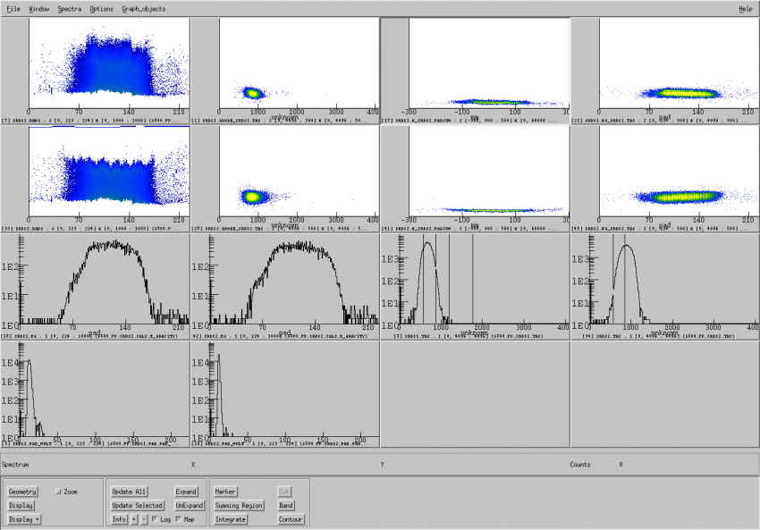
- Check Spectcl window S800_CRDCS.win (see figure below) to verify the good performance of the detectors. (The spectra for each CRDC can be checked separatelly in windows s800_CRDC1.win and S800_CRDC2.win)
- Spectra crdc1.raws and crdc2.raws (top and middle spectra in the leftmost (first) column)
- Each spectra shows the multiple sampled signals from each pad
- The 224 pads are assembled along the dispersive direction
- Width of beam peak is proportional to A1900 p-acceptance in focus optics
- Width is narrower in match optics
- Adjust anode HV to bring fuzzy maximum to around 600-700 channels (saturation of each pad at ~ 1000 ch)
- Spectra crdc1.anode_crdc1.tac and crdc2.anode_crdc2.tac (top and middle spectra in the second column)
- This spectrum is used to ensure that the field in the detectors is uniform and well aligned. If the detector is working properly, then the amplitude of the ANODE signals should not depend on the position of the beam (as shown in the figure below)
- If the field is not well aligned, then there will be a correlation between ANODE signals and TAC signals
- Spectra crdc1.x_crdc1.padsum and crdc2.x_crdc2.padsum (top and middle spectra in the third column)
- It shows the sum over multiple sampled signals from each pad along the (dispersive) x position
- The padsum signals should not show any correlation with the x (dispersive) position
- Spectra crdc1.xg_crdc1.tac and crdc2.xg_crdc2.tac (top and middle spectra in the fourth column)
- It shows the beam distribution in the dispersive (xg) vs non-dispersive (tac) directions
- It is used to ensure that the fragment beam is centered in the detectors
- It is also used to see the effect of the beam blocker (used to stop intense contaminants) in the cocktail beam
- Spectra crdc1.xg and crdc2.xg (bottom spectra in first and second columns)
- It shows the position of the beam in the dispersive direction, evaluated by calculating the “center of gravity”. The peak should be in the middle of the spectra in order to center the beam
- Spectra crdc1.tac and crdc2.tac (bottom spectra in third and fourth columns)
- They correspond to the non-dispersive position of the beam in the CRDCs.
Timing setup
At present, there are three electronic “sources” with time information for ToF calculation: ORTEC TACs, Phillips TDC, and Mesytec MTDC. Some background information can be found here.
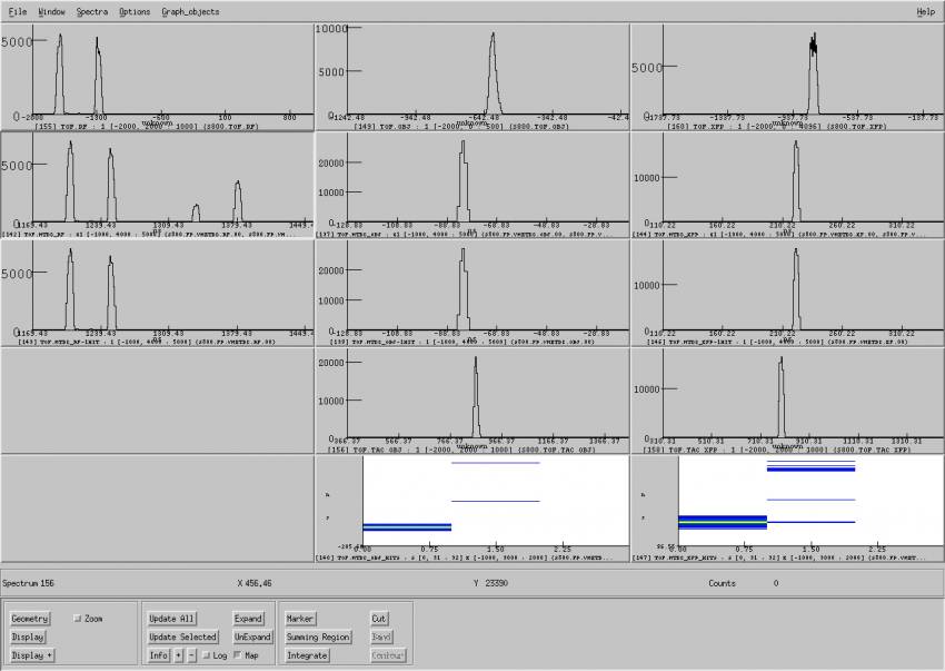
- Select SpecTcl window S800_TOF.win
- The three columns correspond to the RF-FP ToF (left), OBJ-FP (center), and XFP-FP (right)
- The first (top) row corresponds to the Phillips TDC
- The second row corresponds to the MTDC with all the hits included
- The third row corresponds to the MTDC with only the first hit
- The fourth row corresponds to the ORTEC TACs. Note that there is not RF-FP TAC
- The two spectra in the fifth row corresponds to the MTDC summary spectra of OBJ-FP and XFP-FP ToFs (zoomed in). The spectra show the ToF (vertical axis) vs. hit number (horizontal axis). In an unreacted setting, one expects to see the most of the “good” ToF peak recorded in the first hit
- An empty ToF spectrum means that either the delays are not right (and need to be adjusted) or the spectrum range is too narrow
- The MTDC spectra should never be empty because the matching window is sufficiently wide (around 4000 ns)
- If necessary, adjust delays:
- Using the ULM trigger GUI assign TDC-start to one of the Inspect Trigger channels and trigger the scope with it
- Select the timing signals (Delay inspect channels) E1 up, OBJ and XFP with the Delay GUI and look at them in the scope
- Adjust the TDC delays of OBJ and XFP using the delay boxes connected to the CANBERRA CFD 454 in data U6
- Adjust the TDC delays of E1 up, down using the Delay GUI
- In principle, the TACs delays don't need to be adjusted
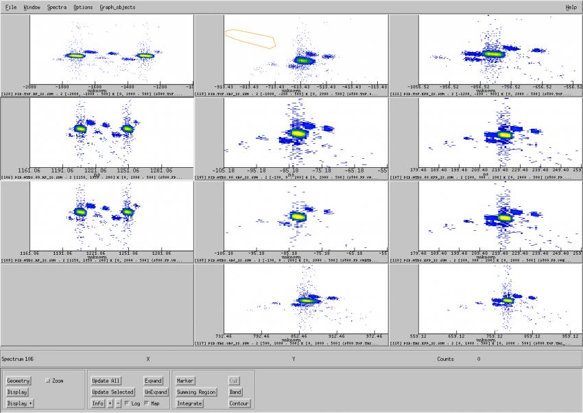
Checking Particle ID and rate at S800 FP
- Select SpecTcl window S800_PID.win in directory /user/s800/operations/spectcl/Windows
- The three columns correspond to the PID determined with the RF-FP ToF (left), OBJ-FP (center), and XFP-FP (right)
- The first (top) row corresponds to the Phillips TDC
- The second row corresponds to the MTDC with just the first hit included
- The third row corresponds to the ORTEC TACs. Note that there is not RF-FP TAC
- You might need to adjust the limits of the spectra to get a good resolution
- Establish PID and measure rate
- Determine the blob that corresponds to the unreacted beam (refer to information on setting from A1900 FP)
- Take gates around the fragment of interest
- Measure the beam intensity the appropriate faraday cup
- Take a run on disk
- Measure the beam intensity again and calculate the average value
- In SpecTcl GUI, click Attach to File and select data file run-xxxx-xx.evt in directory /user/s800/stagearea/experiment/runxxxx, where xxxx stands for the run number * Check the run time and live time from the corresponding scaler file in directory /user/s800/converged_daq/scalers**
- Calculate the rate and purity and compare with the value in the A1900 FP to determine the transmission

