Table of Contents
Venting/pumping-down lower-dipole section
In order to ensure that the beamline in the target area is properly aligned with respect to the beam axis, it is necessary to install a telescope (transit/theodolite) between the last two quadrupole triplets of the analysis line, as well as a “cross hair” plate between the last quadrupole triplet and the target chamber. Although the alignment of the telescope is done by lab staff (e.g. Dave Sanderson), the user is responsible for removing the gate valve D2542 BGV separating the analysis line and the target area. This of course, requires that the lower-dipole section is properly vented. The venting and pumping-down processes are generally done by a instrument scientist.
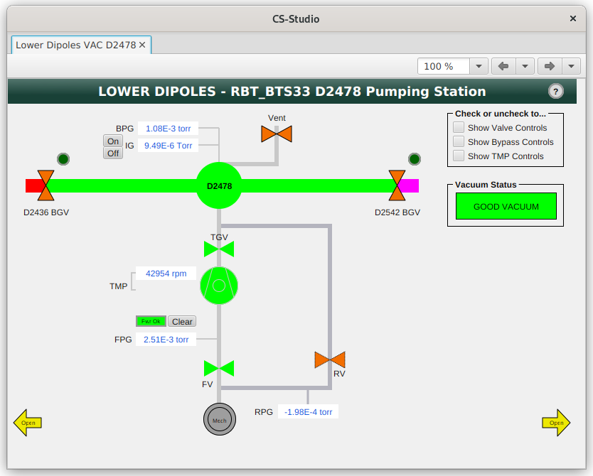
The venting (and pumping) process is done remotely through CS Studio Phoebus. Its page can be found on the EXP network through FRIB EXP Main → S800 → Vacuum Main (Primary Pages) → Lower Dipoles and is shown below.
Instructions on how to vent/pump-down this section are described below.
Venting analysis-line lower-dipole section
- Notify the Control Room that EXP alarms may occur.
- Ensure that beamline gate valves D2436 BGV (between intermediate image area and the lower-dipole section) and D2542 BGV (between lower-dipole section and target area) are closed.
- Ensure that the ion gauge RBT_BTS33:IG_D2478 is turned off.
- Check the box next to “Show Valve Controls”, and close the Turbo Gate Valve (RBT_BTS33:TGV_D2478) by clicking Close.
- Check the box next to “Show TMP Controls”, and turn off the TMP (RBT_BTS33:TMP_D2478) by clicking Off.
- Ensure that the beam chamber is isolated and double-check the ion gauge is off, and open the vent valve (RBT_BTS33:VV_D2478), and observe that that the pressure reading of the beamline Pirani gauge (RBT_BTS33:BPG_D2478) raises slowly.
- After the section is vented (reached at atmospheric pressure), the vent valve should close automatically.
Pumping-down analysis-line lower-dipole section
- The beamline gate valves D2436 BGV and D2542 BGV, the vent valve, the turbo gate valve, and the roughing valve (RV) should be all closed. The foreline valve (FV) should remain open. The ion gauge should remain turned off. The vacuum status should be red with “BAD VACUUM”.
- Close FV and then open RV to start pumping down the beam chamber with the roughing pump. You can monitor the BPG reading (RBT_BTS33:BPG_D2478:VP_RD) by plotting it.
- As the pressure goes down, the vacuum status should become yellow with “POOR VACUUM”. Wait until the BPG reading reaches below 100 mTorr.
- Close RV and open FV, turn TMP on.
- Wait until TMP reaches at normal rotation and open TGV, and the vacuum status should become green with “GOOD VACUUM”.
- Wait until pressure goes below 1 mTorr, and then turn on the ion gauge RBT_BTS33:IG_D2478.


