Table of Contents
Introduction
CoBo uses TI's LMK04800 family of Low-Noise Clock Jitter Cleaner with Dual Loop PLLs. In Cobo 0.2v and CoBo 1.0v LMK04803B is used. The internal VCO of the PLL is designed to run at 2 GHz in our application.
CoBo LMK04803B PLL is responsible for receivering the Global Master Clock (GMC) from Mutant via the MicroTCA backplane on CLK3. After receiving the “dirty” GMC clock the LMK04803B attempts to clean the jitter and lock the PLL1&PLL2 in order to generate multiple clocks.
There are two clock inputs and 12 outputs for CoBo's LMK04803B. The 1st input is CLKin0 which is connected to the GMC clock. There is some feedback logic that sits in between the LMK04803B and Mutants GMC buffer. The additive jitter of that logic is described here. The 2nd input is CLKin1, in CoBo 0.2v this is connected to MCH clock. However, in CoBo 1.0v a backup local oscillator is used instead. Therefore, by using CLKin1 with a local oscillator, it is possible for CoBo 1.0v to use the local 100MHz clock as a back up clock in case GMC doesn't exist or if you want to run CoBo in standalone mode.
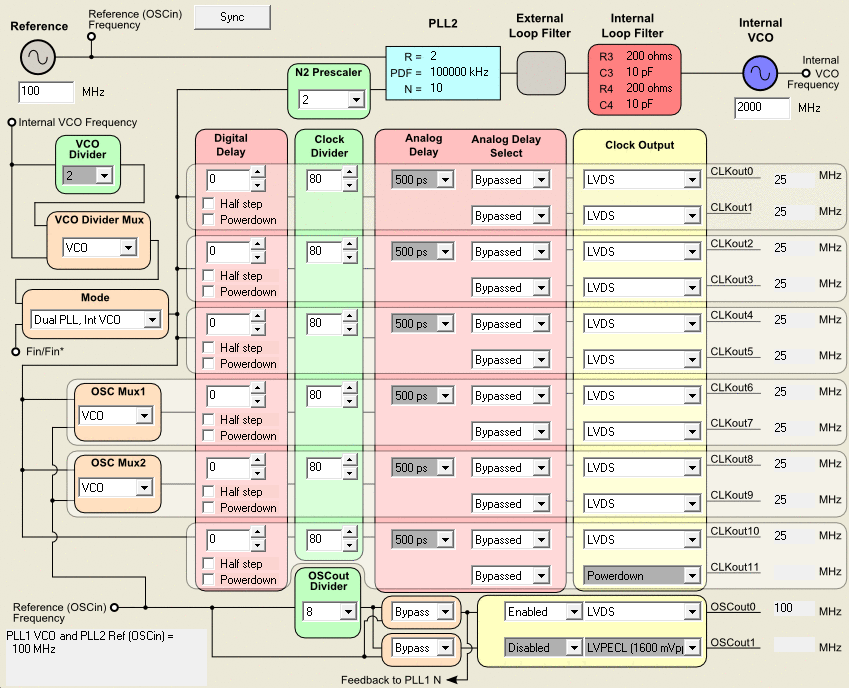
The 12 clock outputs are CKWs and CKRs (passed to Asads and FPGA – total 10 clocks), a buffered version of the VXCO clock, and a programmable clock.
CLKout0 = Asad1 CKR
CLKout1 = Asad0 CKR (settings are tied with CLKout0)
CLKout2 = Asad3 CKR
CLKout3 = Asads CKR (settings are tied with CLKout2)
CLKout4 = FPGA CKR
CLKout5 = FPGA PLL CLK (for testing or driving any logic inside of FPGA at 25MHz) (settings are tied with CLKout4)
CLKout6 = Asad1 CKW
CLKout7 = Asad0 CKW (settings are tied with CLKout6)
CLKout8 = Asad3 CKW
CLKout9 = Asad2 CKW (settings are tied with CLKout8)
CLKout10 = FPGA CKW (settings are tied with CLKout11 – not connected on PCB)
OscOut0 = FPGA buffer VXCO
CKR and CKW
CKR and CKW are AGET chip Read and Write clocks. These clocks are passed from LMK04803B to an LVDS buffer on CoBo and sent over VHDCI cables to Asads. We have tested the communication with a 10 meter VHDCI cable with CKW running at 100MHz (For longer cables consider setting JP9 to 1-2). The table below lists the trace lengths on the PCB. AS* are the signals from the LMK04803B to the LVDS buffer, CK* (shorter traces) are the signals from the LVDS buffer to the VHDCI connector.
| Name | Node Count | Routed (mil) | |
|---|---|---|---|
| AS0_CKR_N | 2 | 6940.808 | |
| AS0_CKR_P | 2 | 6940.416 | |
| AS0_CKW_N | 2 | 6886.032 | |
| AS0_CKW_P | 2 | 6885.735 | |
| AS1_CKR_N | 2 | 6944.301 | |
| AS1_CKR_P | 2 | 6948.342 | |
| AS1_CKW_N | 2 | 6897.755 | |
| AS1_CKW_P | 2 | 6896.847 | |
| AS2_CKR_N | 2 | 6958.892 | |
| AS2_CKR_P | 2 | 6956.581 | |
| AS2_CKW_N | 2 | 6895.987 | |
| AS2_CKW_P | 2 | 6898.616 | |
| AS3_CKR_N | 2 | 6938.05 | |
| AS3_CKR_P | 2 | 6943.109 | |
| AS3_CKW_N | 2 | 6902.934 | |
| AS3_CKW_P | 2 | 6892.022 | |
| CKR_1_N | 2 | 1331.634 | |
| CKR_1_P | 2 | 1331.632 | |
| CKR_2_N | 2 | 1300.127 | |
| CKR_2_P | 2 | 1302.286 | |
| CKR_3_N | 2 | 1331.444 | |
| CKR_3_P | 2 | 1318.534 | |
| CKR_4_N | 2 | 1299.578 | |
| CKR_4_P | 2 | 1302.145 | |
| CKW_1_N | 2 | 2222.98 | |
| CKW_1_P | 2 | 2228.041 | |
| CKW_2_N | 2 | 2193.289 | |
| CKW_2_P | 2 | 2191.66 | |
| CKW_3_N | 2 | 2228.182 | |
| CKW_3_P | 2 | 2226.657 | |
| CKW_4_N | 2 | 2193.402 | |
| CKW_4_P | 2 | 2191.547 | |
It is possible to change the frequency of CKR/CKW using getEccClient or GetController. Currently, CKR is fixed at 25 MHz. CKW can be programmed to any frequency within the specs of the LMK04803B and the AGET chip.
Synchronization
To synchronize the LMK04803B clocks on a single CoBo board, one has to send a pulse (at least 0.5ns positive pulse, see datasheet for the minimum length of this pulse and polarity) from the FPGA to the LMK04803B chip using PLL_SYNC signal on pin F8. The length of the PCB trace is 1320.475 mils.
The default configuration requires the Mutant and the CoBo to calibrate the GMC/WSCA links between them first. After that the Mutant sends a SYNC command to all CoBos on the WSCA line. CoBo uses that command to sync its own clocks.
PLL Configuration
The default configuration of the PLL is
0x00000A00
0x00000A01
0x00000A02
0x00000A03
0x00000A04
0x00000A05
0x11110006
0x11110007
0x01110008
0x55555549
0x9140410A
0x0400000B
0x0B0C006C
0x1B12902D
0x1200000E
0x8000800F
0x01550410
0x000000D8
0x01010019
0xAFA8001A
0x1C0000DB
0x002000DC
0x0180015D
0x0200015E
0x001F001F
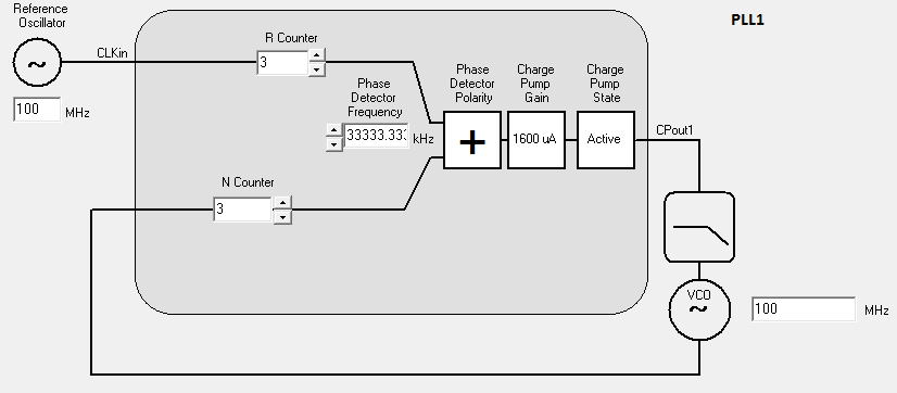
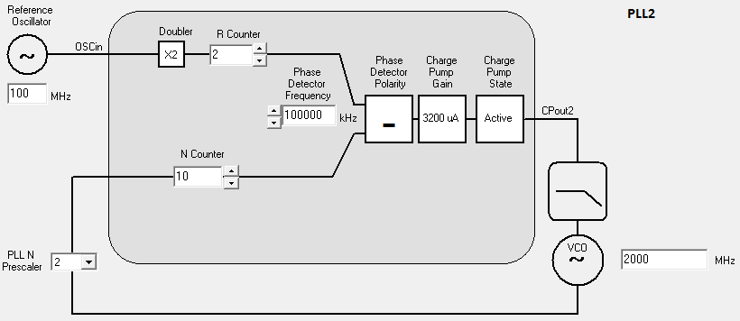
The settings for this configuration are depicted in the figures below
Frequency Accuracy
It is possible to program LMK04803B to lock on certain conditions. Take a look at section 9.6 in the datasheet.
From (3) for PLL1, the frequency accuracy is:
PLL1_ppm = 2e6 * PLL1_WND_Size * Fpd1 / PLL1_DLD_CNT
The default values are:
PLL1_WND_Size is 40 ns
PLL1_DLD_CNT is 1024
Fpd1 = 33.333 MHz
PLL1_ppm = 2e6 * 40e-9 * 33.333e6 / 1024 = 2604.141
If the GMC clock supplied by Mutant doesn't meet PLL1_ppm then PLL1 will not lock to this frequency. As a result, causing timestamp issues in the data. See this page as an example.
The user must change the values of PLL1_WND_SIZE and PLL1_DLD_CNT if they want to restrict GMC to smaller ppm values.
For the second PLL:
PLL2_WND_Size is 3.7 ns
PLL1_DLD_CNT is 8192
Fpd2 = 100 MHz
PLL2_ppm = 2e6 * 3.7e-9 * 100e6 / 8192 = 90.33
Clocks and PLL Status
The default configuration above allows the user to check status of LMK04803B is directly as follows:
- CLKin0 Status (FPGA_PIN E9) indicates whether CLKin0, being supplied by the mutant GMC, has been lost or not. A logic 1 means the clock is lost.
- CLKin1 Status (FPGA_PIN F9) indicates whether CLKin1, being supplied by the local dedicated 100 MHz oscillator, has been lost or not.
- LD_MUX status (FPGA_PIN A13) is by default configured to indicate whether PLL1 of LMK04803B has successfully locked to Mutant's GMC. i.e. LD_MUX = PLL1 DLD
- HOLDOVER_MUX status (FPGA_PIN D12) is configured to indicate whether PLL1&PLL2 of LMK04803B has successfully locked to Mutant's GMC AND VCXO respectively. HOLDOVER_MUX = PLL1 & PLL2 DLD
Misc
To run CoBo in Standalone mode i.e. without Mutant GMC:
For CoBo 0.2v
- change the R11/Mode = 0x06
- Using LEMO configuration from EccClient/GetController. Assign PLL_SYNC signal to one of the LEMOs.
- After you power up CoBo and load hardware and configure, Bring PLL_SYNC on the LEMO to HIGH then back to LOW.
- you can sync multiple cobos this way using the external LEMOs.
Alternative method:
- change the R11/Mode to 0x06
- change R11/SYNC_EN_AUTO to 1
- This will sync a single cobo only.
For CoBo 1.0v:
Use the above two methods available for CoBo 0.2v, or:
- Enable Clkin1 in R13
- R13/CLKin_SELECT_MODE = 0x01
- For syncing you can either do the LEMO method or the SYNC_EN_AUTO method
Below is an ecc script example of CoBo 0.2v running PLL2 only. The SYNC polarity must be inverted if Mutant is plugged in (regardless of GMC being supplied or not)
connect node 192.168.40.50
load hardwareDescription_fullCoBoStandAlone.xcfg
connect device pll
pll-reset
pll-write 0x00020000
pll-write 0x00000A00
pll-write 0x00000A01
pll-write 0x00000A02
pll-write 0x00000A03
pll-write 0x00000A04
pll-write 0x00000A05
pll-write 0x11110006
pll-write 0x11110007
pll-write 0x01110008
pll-write 0x55555549
pll-write 0x9140400A
pll-write 0x3401A00B
pll-write 0x0B0C006C
pll-write 0x1B12902D
pll-write 0x1200000E
pll-write 0x8000800F
pll-write 0x01550410
pll-write 0x000000D8
pll-write 0x01010019
pll-write 0xAFA8001A
pll-write 0x1C0000DB
pll-write 0x002000DC
pll-write 0x0180015D
pll-write 0x0200015E
pll-write 0x001F001F


