historical_design_notes
Table of Contents
Requirements for the Prototype (Mittig)
- The maximum size foils we want to test are 114.7 mm*114.7mm, be mounted on 200mm*200mm printed circuit boards
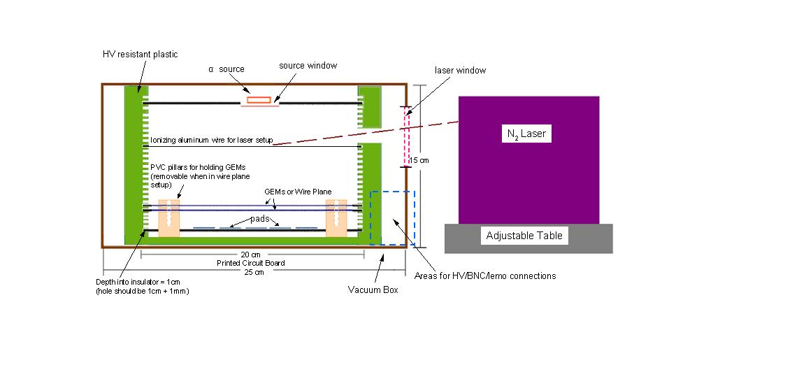
- There will be a UV-photodiode above the Kathode to produce electrons in a semitransparent foil, isolated from the cathhode (Vmax=5kV) (2 connections)
- For calibration, an alpha particle source will be fixed face down over a hole in the cathode
- Next to the Kathode there will be 1 or 2 gems, mounted on a printed circuit board, at a variable distance, needing 4 HV connections
- The voltage division will be done externally, this means 5 HV feed-throughs are needed (+1 spare)
- The signals will be collected on a segmented anode, with maximum 5 signals to be transmitted to external preamplifiers
- The most simple seems to be a drawer like device, that allows easily to change configuration, distance of drawers 2 printed board, thicknesses, width 1+ε
- The final device should be clean and dust-free; all manipulations should be done in a clean environment
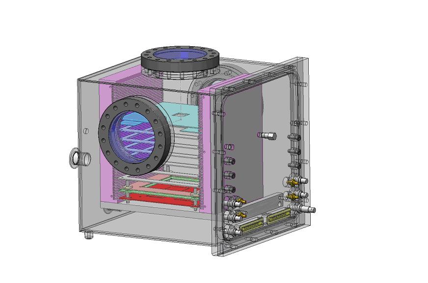
Updated Design July 29,2008
- Designed to be used with either a laser as the ionization source or an alpha source.
- Can be rotated as needed to access particular window.
- Mounting of GEMs is flexible in order to study gain dependence on the GEM spacings.
- Outer box is vacuum tight, enabling various gas mixtures to be introduced into the chamber. Also has the ability to be run at reduced pressures (as low as 0.2 atmospheres).
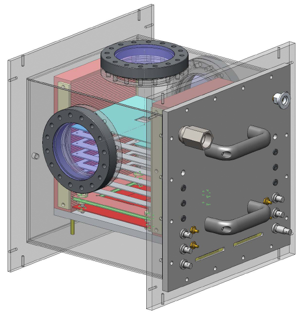
Updated Design August 8,2008
Modifications from previous design include:
- The addition of handles to facilitate opening the device.
- Pressure relief valve has been modified to utilize a more reliable manufactured design; valve releases at 15psi.
- End plate has been extended past the windows so that the chamber can rest on any face (with the exception of the end with the connectors).
- Feet have been added underneath the internal drawer to provide the proper offset when opening and closing the chamber.
- Stops are included on both sides of the internal tray structure to secure all trays in place.
- Document describing modes of operation and orientation of test stand :teststandorientation_080808.pdf
Minutes from the Design Review (updated: August 11, 2008.)
Action Items:
- Craig will remove the tapped holes from the corners of the box.
- Craig will provide a list of parts to be machined with 2D drawings on Wednesday; the materials required for each part will be identified.
- Abby will review and approve the materials via email Thursday.
- Jay will provide an estimate of the shop time required for the job on Friday.
Notes:
- The large components of the assembly will be sent out to be cut via water jet.
- The stainless pieces that form the external walls of the box will be welded from the inside and tacked on the outside to minimize bowing of the end plate.
- Once the external structure is assembled the box (minus the Al door) will be set put for electropolishing.
- The window flanges will be mounted after the electropolishing is completed.
- The job is likely to be in the 40-80+ hour category, but Jay will provide a more realistic estimate.
- Once the time required has been established Thomas G. will be contacted to schedule the work in the shop.
historical_design_notes.txt · Last modified: 2009/04/23 11:58 by 127.0.0.1


