This is an old revision of the document!
Table of Contents
GRETINA LN filling system
Status (June 2013)
LN supply ON (valve 2 in wall manifold) is c0.2/relay #1, i.e. open main supply to GRETINA with opv 1
NOTE: don't use 'cooldown' for manifold 0 (wall manifold). If bypass valve c0.3 is opened LN from the Dewar actually will flow back through valve c0.1 (even closed) into vent line, as Dewar pressure is higher the building supply pressure.
| manifold | ovl Pt100 | ovl Pt100 #adc | valve | valve #relay |
|---|---|---|---|---|
| 0 | n.a. | (back pressure) | c0.3 | 2 |
| 1 | c32.1 | 182 | c12.1 | 40 |
| 2 | c32.1 | 182 | c12.1 | 40 |
| 3 | c33.1 | 183 | c13.1 | 48 |
| 4 | c33.1 | 183 | c13.1 | 48 |
| detector | LN ID | ovl Pt100 | ovl Pt100 #adc | valve | valve #relay | manifold |
|---|---|---|---|---|---|---|
| Dewar | 0 | c30.1 | 180 | c0.4 | 3 | 0 |
| Q1 | 1 | c1.2 | 7 | c12.3 | 42 | 1 |
| Q2 | 2 | c2.2 | 13 | c11.2 | 33 | 2 |
| Q3 | 3 | c3.2 | 19 | c13.2 | 49 | 3 |
| Q4 | 4 | c4.2 | 25 | c13.5 | 52 | 4 |
| Q5 | 5 | c5.2 | 31 | c13.3 | 50 | 3 |
| Q6 | 6 | c6.2 | 37 | c12.2 | 41 | 1 |
| Q7 | 7 | c7.2 | 43 | c13.4 | 51 | 4 |
| Q8 | 8 | c8.2 | 49 | c11.4 | 35 | 2 |
| Q9 | 9 | c9.2 | 55 | c13.6 | 53 | 4 |
| Q10 |
| Wall Box | description | valve | valve #relay |
|---|---|---|---|
| 1 | building LN | c0.1 | 0 |
| 2 | to Gretina | c0.2 | 1 |
| 3 | DO NOT USE | c0.3 | 2 |
| 4 | exhaust | c0.4 | 3 |
filling buffer Dewar: opv 0 & opv 3
NEVER open wall box valve 3 (opv 2), LN from buffer Dewar is then released into vault via exhaust!
Connector-Channel map LNmap
Misc
part numbers
- LN sensor (new style): http://www.omega.com/ppt/pptsc.asp?ref=PR-10&Nav=hear01, 1/8 DIAMETER RTD PROBES, P# PR-10-2-100-1/8-2.5“-E, NOTE: 2.5” is custom made
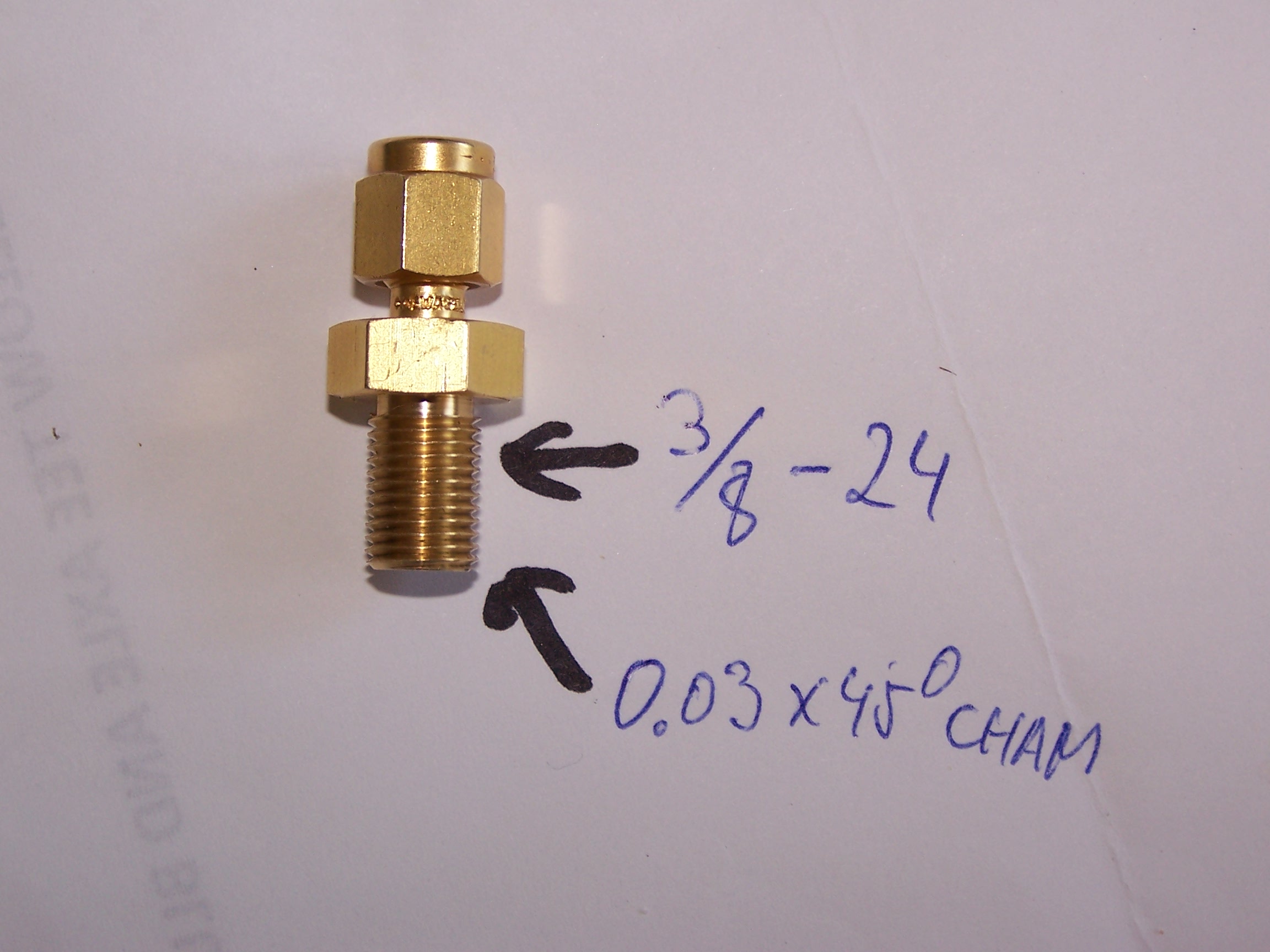
- Tube to Pipe fitting for PT100 (Swagelok # B-200-1-4BT; 1/8 Tube X 1/4 NPT Bored thru), NOTE: thread for needs to be modified. photo of modified fitting: fittingpt100.jpg
- Replacement Springs from Lee Spring Company :P# LP 020E 04 S316 the correct fit that will only allow 1-3 PSI max.