Pulser Ramp Calibration
In a pulser ramp calibration, a tail pulser is used to pulse a system at many equally spaced pulse amplitudes. This can be used to test the linearity of the system and to find the zero offset. We have used it for both the Si ASICs and the CsI preamps. Note that the ASIC pulser distribution system may itself be nonlinear.
Setup
As noted above, the ASIC Motherboards have an onboard pulser distribution system. Simply plug the PULSE OUT of the BNC PB-5 pulser into the appropriate pulser input in the inspect channels. It is recommended that you trigger the acquisition off of the pulser TRIG OUT rather than the ASIC ORs to reduce noise. The RS-232 port on the back of the pulser needs to be connected via a serial cable to a Terminal Server, which connects to the lab network via Ethernet cable.
Calibration
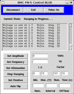
 Set the pulser to remote mode on its local interface, then open the control program, pictured here. Several versions exist in the HiRA SVN repository in the directory HiRASoft/Online/PulserControl. Some of these are formatted to trigger on their own, while others only trigger when they receive a positive (TTL) signal on their EXT TRIG input; make sure you pick the correct one. Start the program in Tcl/Tk by typing
wish pulserGUI_BLUE.tcl
on a Linux command line. It doesn't matter what machine you're logged into since the pulser is connected directly to the network. Click connect to start controlling the pulser; it will give you an error if the pulser is not in remote mode, is not connected to the network, or already is being controlled, although it won't be obvious which of these is the case.
Often you'll run without ramping to figure out the voltage range that you want; click “Pulse On” and set the amplitude a few times until you're convinced. Note that the pulser has a maximum amplitude of 10V. Then, click “Pulse Off” and set the amplitude to your starting value. This isn't technically necessary, but reduces the likelihood of stray pulses before and after the ramp. Set your starting voltage, ending voltage, number of steps, and time for each step on the line next to the “Start Ramping” button; descriptions of each entrybox are immediately below it. Then begin your run, click “Start Ramping”, and sit back and relax. When you start a new ramp, make sure you set the amplitude to your starting value again.
Starting a ramp causes the pulser to assume some default conditions, so if you don't see any pulses, make sure the trigger and polarity are still set correctly. If they aren't, you may have to modify the control software. If you need to end a ramp early, just click “Stop Ramping”; note that turning the pulse off or on at the top of the GUI has no effect.
Analysis
![]() Someone who has used the pulser analysis program should describe it here.
Someone who has used the pulser analysis program should describe it here.

