Table of Contents
Overview
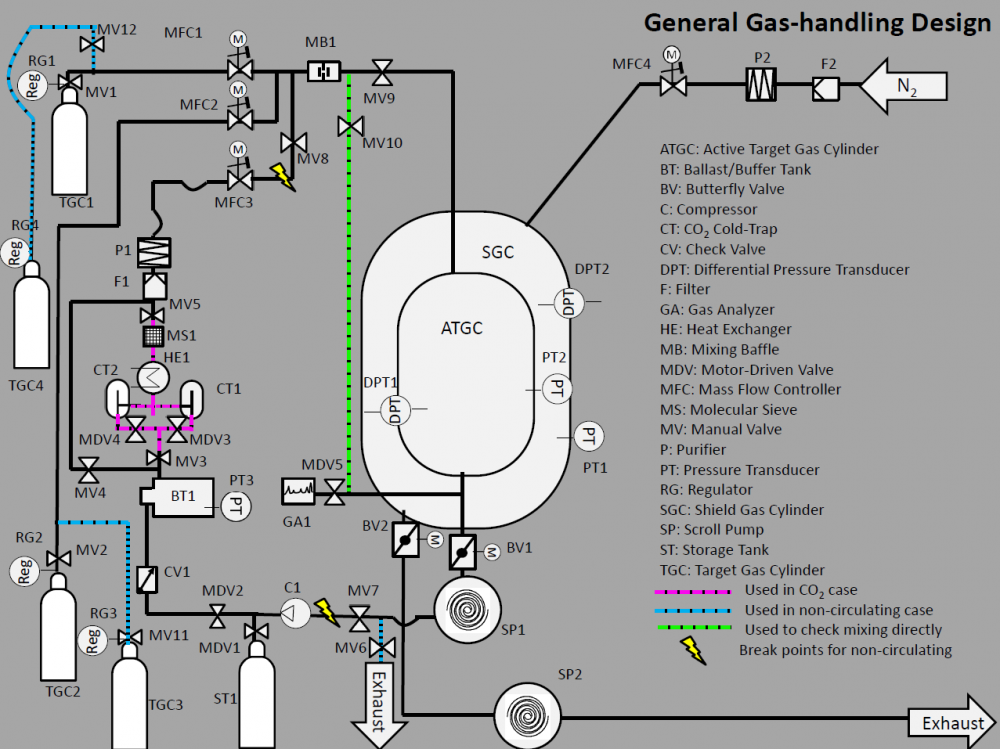
The purpose of the gas handling system is to provide the AT-TPC (Active Target Time Projection Chamber) target and insulation chambers with a precise gas mixture at a stable pressure, allowing for the use of several gas mixtures over a large range of pressure. In order to preserve our (often moderately expensive) gases, we require a recirculation system with purification capability and, ideally, the ability to monitor gas composition (i.e. purity and mixture ratio).
This overview was given at the NSCL Graduate Student Seminar November 12, 2012.
Deliverables
The necessary pressure stability and purity are taken from calculations done by D. Suzuki (pressurestabilitydsuzuki.pdf). Ultimately the calculations imply pressure fluctuations of the target/detector gas must be within 0.1% to keep the uncertainty in signal gain within 1%. The exact gas composition must be maintained within 0.03% to keep the uncertainty in signal gain within 1%. If the maximum drift velocity fluctuation must be within 0.02%, then the exact gas composition must be maintained within 0.01%, however drift velocity changes are also related to contaminants (see next paragraph).
The tolerable contaminant concentration, assuming the major contaminants are oxygen and moisture, are taken from S.Amendolia et al. and S.Afanasiev et al., each of which are studies of previous TPCs. Given a drift length of one meter, the concentration of oxygen and moisture must be kept below 10-20 parts per million to achieve a maximum drift velocity attenuation of 1%. To accomplish the required gas purification the two previously mentioned references cycle the full detector volume within a 90 minute period. For a 460 liter volume, this corresponds to a flow rate of roughly 5 standard liters per minute.
Thus, we plan to obtain:
- <0.1% pressure fluctuation
- <0.03% composition change
- <10ppm oxygen & moisture contamination
- ~90min cycle time
Design
General Comments
The design of the gas handling system is intended to be general enough to be able to handle several types of gases as well as operate in a circulating or non-circulating mode. Switching between these modes is intended to require minimum effort due to the use of designated 'break points'. For more complicated gas mixtures, modifications would likely be required. For example, H2 might require extra monitoring and 3He would require extra special care in system controls to be sure large amounts weren't inadvertently lost. However one should note that no component selected for the original design is inconsistent with the use of these gases.
Currently we envision a circulating system for the target chamber and a non-circulating system for the shield gas chamber, assuming N2 is used as a shield gas. Special equipment must be used in the circulation of gas mixtures containing CO2 as it is a purifier poison. Thus we must remove the CO2 from the gas mixture before purification and add more CO2 after.
Pumping
A scroll pump is used to evacuate gas from the AT-TPC in order to ensure minimum contamination of the gases used. The scroll pump is oil-less, however the tip seals are known to introduce dust into the flow gas. The following paragraph discusses the specifications our scroll pump must meet along with justifications for each requirement.
The ultimate vacuum achievable must be below 0.1Torr as this pressure is required for a proper zeroing of the pressure gauges (e.g. the 622A Baratron). The maximum outlet pressure must be below 15psig so we can reasonably reduce the system pressure back down to that required in the chamber (<760torr). Leak tightness must be a minimum, where scroll pump industry standard seems to be <1e-6 standard cubic centimeters per second. The pump must be hermetically sealed and lubricant free within the vacuum envelope. Minimum volumetric flow must be above 0.2 cubic feet per minute to obtain 5slpm flow. Ideally the pump would require minimum maintenance and be light weight.
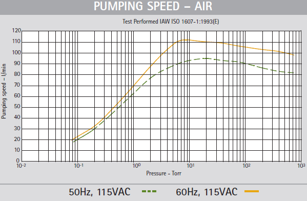
After going through the purchase requisition process (requisition #17598), we arrived at the Agilent SH-110 scroll pump 1-phase. Pumping performance is shown in the image below, as seen in the previously mentioned pdf. We describe specific pump performance in the Tests section below.
NOTE: The Agilent scroll pump will NOT be suitable for pumping flammable gases, such as Hydrogen. We can still use this pump for the shield gas, however. For flammable gases, we can use the Edwards XDS10 scroll pump.
Pressure Control
Pressure in the chamber is controlled by using a fixed inlet flow rate and a variable outlet flow rate. The outlet flow rate is adjusted by the use of a butterfly gauge between the chamber and scroll pump which can communicate with a gauge reading the chamber pressure. Currently for this purpose we use the MKS T3BiA Butterfly Valve coupled with the MKS 622A Baratron (note MKS only makes the 622B baratron). The butterfly valve acts as a pumping choke, where the amount of valve closure is directly related to the chamber pressure via a proportional, integral, derivative (PID) method. Communication with the T3BiA is through RS232 via a list of custom commands (a more complete list is here). Valve performance is described in the Tests section below.
In order to maintain a positive pressure difference between the target gas and shield gas chambers we will require a differential pressure transducer, so as to not depend on the absolute calibration of each chamber's baratron. The current candidate for differential pressure monitoring is the MKS 226A Baratron.
Compression
In order to mitigate the pressure drop suffered by the gas due to system components (especially the purifier), the circulated gas must be compressed after evacuation from the chamber without contaminating the flow gas. We require a compressor which can take an inlet pressure on the order of 10s of Torr, as this will be our minimum desired pressure, and which obtains an outlet pressure high enough to suffer subsequent pressure drops in the system.
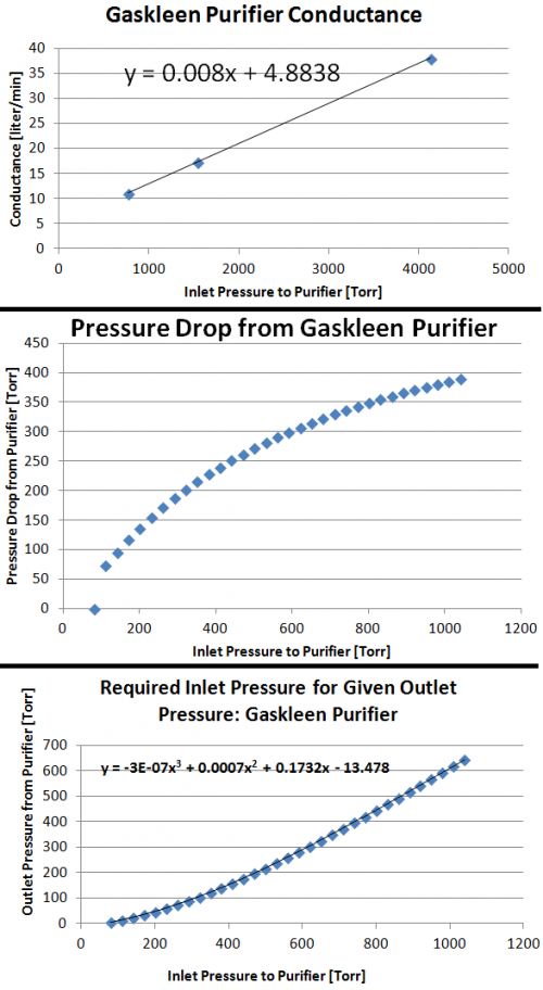
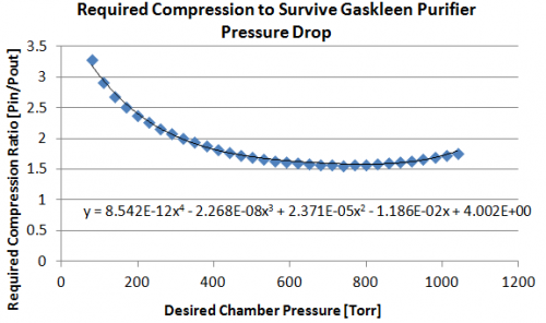
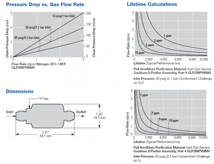
Our primary pressure drop will be from the purifiers (An image detailing pressure drop as a function of flow rate and inlet pressure is in the Purification section. Via information given in the Pressure Drop vs Flow Rate for given inlet pressures, we can calculate the purifier conductance [l/min] as a function of inlet pressure (Conductance = Throughput/PressureChange –> C= (Pin/dP)(dV/dt)). Pressure drop across the purifier at our flow rate of interest (5 liters per minute), is then computed with our new conductance. For each chamber pressure we can then specify what the compression must be in order survive the pressure drop from the purifier to arrive back at our desired chamber pressure. The following figures show this process graphically. For example, we see we require compression up to ~275Torr for an 80Torr chamber pressure (compression ratio of ~3.3) and a compression up to ~1190Torr for an 760Torr chamber pressure (compression ratio of ~1.58).
Purification
Purification is required in the circulating system to mitigate the problems due to leaks and out-gassing materials, however we might want to consider in-line purification for gas fresh from the cylinder as well. In the circulating system the primary contaminants to remove in purification are O2 and H2O.
We would like a minimum level of contamination from O2 and H2O, though we require less than 10 parts per million concentration. The purifier must be able to remove dust contamination, as this will be produced by the scroll pump used to evacuate the chamber. The purifier must allow for the flow rate required to cycle the chamber gas within 90 minutes (In our case ~5slpm). Ideally the purifier will result in a minimum pressure drop such that a minimal amount of compression is required post-evacuation from the chamber.
Currently the most promising candidate for this task is the Gaskleen II Purifier. This purifier removes H2O, O2, CO2, and CO to <1ppb and has a 1×10⁹ retention of particles >0.003μm up to a flow of 5slpm. Regarding costs, John Yurkon obtained a quote from Systems Specialties in March 2011 for $1660 each.
Below is an image describing the Gaskleen Purifier II's performance, which is also included in the above mentioned pdf.
Gas Storage
Expensive gases must be stored when not being used in the system. The two options which exist are equivalent volume containers, which are large but require little in the way of safety, and high-pressure containers, which are smaller but will require ORCBS approval. Using the Gast MAA V109-MB compressor mentioned in the Compression section, we would only be able to compress 500liters of gas at 760Torr to a volume of 144liters (at 2625Torr). Thus to opt for the high-pressure storage we would require an alternative compressor.
An example of a high-pressure storage option is the High Pressure Inert Service Empty Gas Tank fromMcMaster-Carr.
Buffer Volume
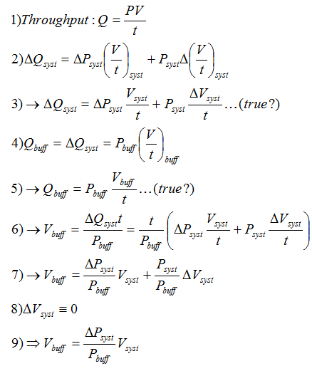
In an ideal gas-handling system, no extra volume would be required to deal with surges in gas-flow. However, it seems unlikely the interaction between the mass flow controllers (see Flow Control section), butterfly valve (see Pressure Control section), and compressor (see Compression section) will be so smooth. We determine the volume of the buffer tank based on the estimated change in throughput(Q=[PV]/t) in the system. As seen in the figure below, we estimate the buffer volume is equal to the ratio of system-pressure fluctuation and buffer volume pressure multiplied by the system volume. This assumes steps 3 and 5 are valid. ΔPsyst will be estimated based on the compression tests below, Vsyst is taken as chamber volume for a rough estimate, and Pbuff is taken as the compressor output pressure.
CO2 Removal
CO2 must be removed from a gas mixture before purification of the other components because it is a purifier poison. More can be added in from a cylinder because it is inexpensive. A cold trap will be used to freeze the CO2 from the gas mixture and a heat exchanger must be used to heat the gas back up to room temperature. The cold trap will need to be heated periodically to remove CO2, so a second cold trap will be used while bypassing the first.
John Yurkon says the NSCL is capable of manufacturing a liquid nitrogen cold trap. Testing will have to be done to determine if a heat exchanger is necessary. It is possible a low budget option such as heat wrap around a helical copper coil will do. MKS sells heater jackets for stainless steel tubing.
Flow Control
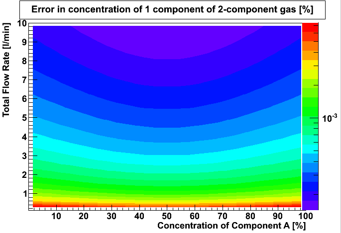
Performance of the pressure control system (see Pressure Control section above) relies on having a consistent flow of gas in the system. Both the flow of circulated gas as well as new gas introduced into the system must be controlled. As we require a precise mixture of gas, the mass flow controllers must communicate in real time to coordinate the relative gas flow. The mass flow control must have deviations small enough so as to not change the overall composition by more than 0.03%, as described in the Deliverables section.
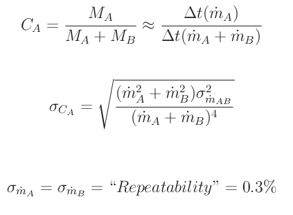
For a two-part gas (gas A+ gas B), concentration of component A is CA=[MA</sub]÷[M<sub>A+MB]. We can substitute time multiplied by mass flow for mass and, via simple error analysis and the fact that mass flow error for gas A is the same as the mass flow error for gas B, we arrive at the following result for the concentration error.
In order to result in a percent uncertainty, we divide the concentration error by the concentration. Using the repeatability quoted for the MKS πMFC PFC-50/60 mass flow controller (0.3% of flow reading), we obtain the following fractional concentration error.
The MKS πMFC PFC-50/60 operates with several different gas types over an adequate range of flow rates (see the pdf).
Gas Supply
The initial charge of gas will be supplied by high pressure cylinders and mixed via mass flow controllers. A large volume (at normal temperature and pressure,NTP=298K,760Torr) is required for the non-circulating configuration as well as for CO2, as it must be removed from the mixture before purification (see Purification section). For the previously stated situations the examples below will show that it is necessary to have two cylinders outside the secured area in order to allow for changing the gas cylinders during an experiment.
For example, Argon can be procured in a DOT3AA-2400 size K cylinder (see the welding group's supply at the NSCL) which contains 8200 NTP-liters, thus allowing for 27 hours of operation with a 5 liter per minute flow. Similarly, Helium can be procured in a DOT3AA2015 size A cylinder (I borrowed some from Brad Barquest at the NSCL) which contains 6050 NTP-liters, allowing for 20 hours of operation with a 5 liter per minute flow.
Gas will have to be introduced to the system from time to time even when the gas mixture is being circulated due to imperfections in the system. We can likely monitor the pressure in the buffer volume (see Buffer Volume section) and detector volume to decide when more gas needs to be introduced into the system.
Automated Valves
We will use pneumatic valves controlled by solenoids located away from the valve so that the magnetic field isn't a problem. The exact valve type hasn't been selected yet, however likely candidates are provided by Humphrey Products Company or Swagelok.
Purity Monitor
We require that the gas in the system has <0.03% composition change and <10ppm concentration of O2 and H2O. The ideal device would provide real-time analysis of our gas composition with the ability to detect a large range of gases having concentrations from <1ppm up to % levels. Unfortunately such a device is quite expensive, as is explained below, so it might be more cost effective to simply monitor for contaminants.
Two options which meet the above requirements are the Extrel MAX300 LG Gas Analyzer (contact: Brian Regel; brian(dot)regel(at)extrel(dot)com) and the MKS Cirrus2 (contact: Chris Sims; chris_sims(at)mksinst(dot)com). More detailed specifications of the Extrel MAX300 LG are here. However, the quote from Extrel is $66K and a rough quote provided for the Cirrus2 is $44K. So it turns out quadrupole mass spectrometers are expensive.
If we choose to just detect contaminants, we have more options. One such option is the SRI Instruments Multiple Gas Analyzer Gas Chromatograph. However gas chromatographs are difficult to calibrate accurately and have very slow response time. Thus any device other than a quadrupole mass spectrometer would cause us to forfeit the ability to have real-time composition analysis for our full gas composition.
Equipment Organization
We are looking into a surface-mount option for valves and mass-flow controllers to allow for a compact system. All components (except perhaps the purity monitor discussed above) will fit on a single storage rack. We may choose to store the compressor adjacent to the rack if its vibrations prove to be a problem. Ideally the storage rack would be easily movable, such as one of these racks from McMaster-Carr.
System Control
System control will be coordinated by the National Instruments CompactRIO device. The CompactRIO is an automation controller programmed via LabView which can be ordered to accept several different types of analog and digital inputs. National Instruments provides an on-line tool which allows you to build a CompactRIO that works for you. Input slots can be added in increments of 4. The current estimate for the required number of channels is:
- 2 for butterfly valves
- 1 target gas
- 1 Shield gas
- 4 for mass flow controllers
- 2 target gases
- 1 shield gas
- 1 circulated gas
- 2 for differential pressure transducers
- 1 between target and shield gas
- 1 between shield gas and environment
- 1 for gas purity analyzer
- 6 for pneumatic valves
- 2 for re-routing to storage tanks
- 4 for switching between cold traps
- 1 for buffer tank pressure transducer
- 3 in case a third chamber is added
- 1 butterfly valve
- 1 differential pressure transducer
- 1 mass flow controller
19 total
Given the the increments of 4 requirement, this would indicate we need a CompactRIO with 20 slots. We must know each component which will be ordered for the gas handling system to be sure we choose the right slot types.
Surface Mount Manifold
To have a maximum compactness we would like to go with a surface mount manifold for as many gas handling components as this is possible (We need to go with the IGC-II instead of the MPC because the IGC is for 'high purity' applications and it does not use o-rings like the MPC does). Certainly the pneumatic valves and mass flow controllers (via an adaptor) can be directly used with the surface mount manifold. Other components can be tied in via tube-ports which can be placed in positions on the surface mount manifold. To estimate necessary accessories for a surface mount system, we can use the Swagelock IGC-II configurator.
Miscellaneous Parts
To estimate the type and number of parts needed to connect the major components of the gas handling system (e.g. tubing and clamps), we can use the Swagelock IGC-II configurator, assuming surface mount technology is used.
Rough Component Estimate
A mildly outdated list of required components and their costs is here.
This list will evolve and is already in need of an update.
Tests
Pressure Stability
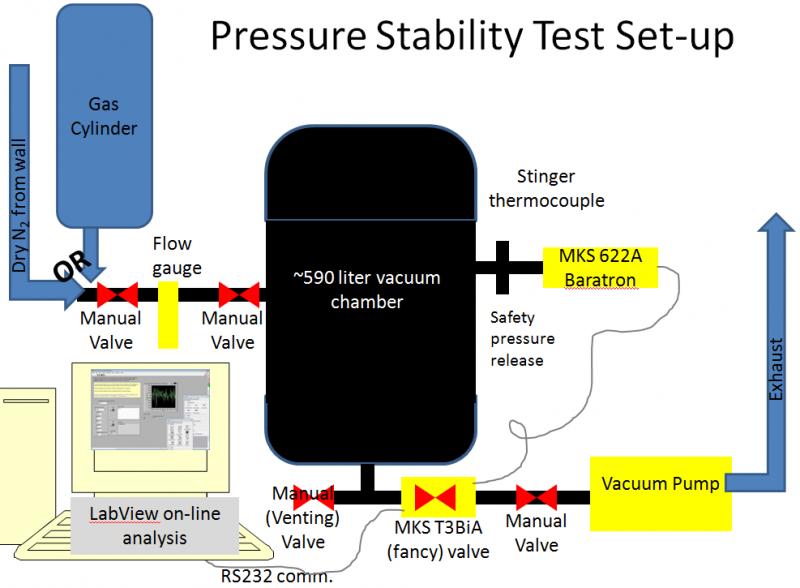
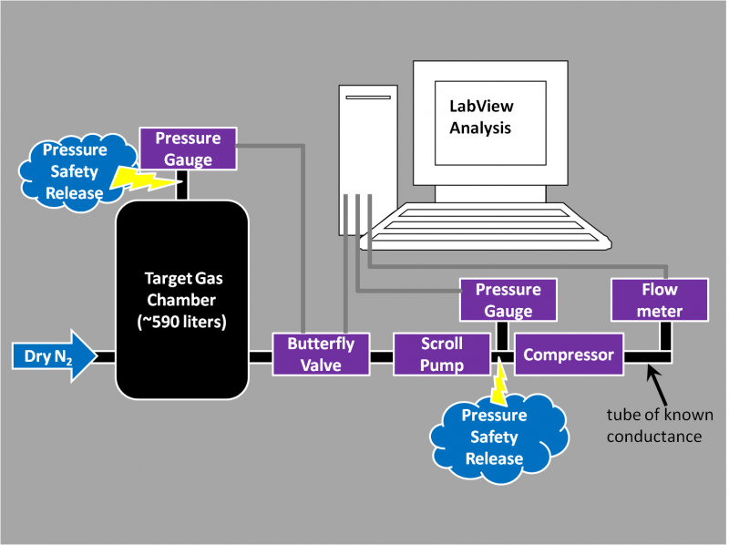
We tested the deviation from a set-pressure as a function of chamber pressure for flow gases N2, 4He, and Ar, using the following set-up.
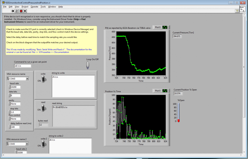
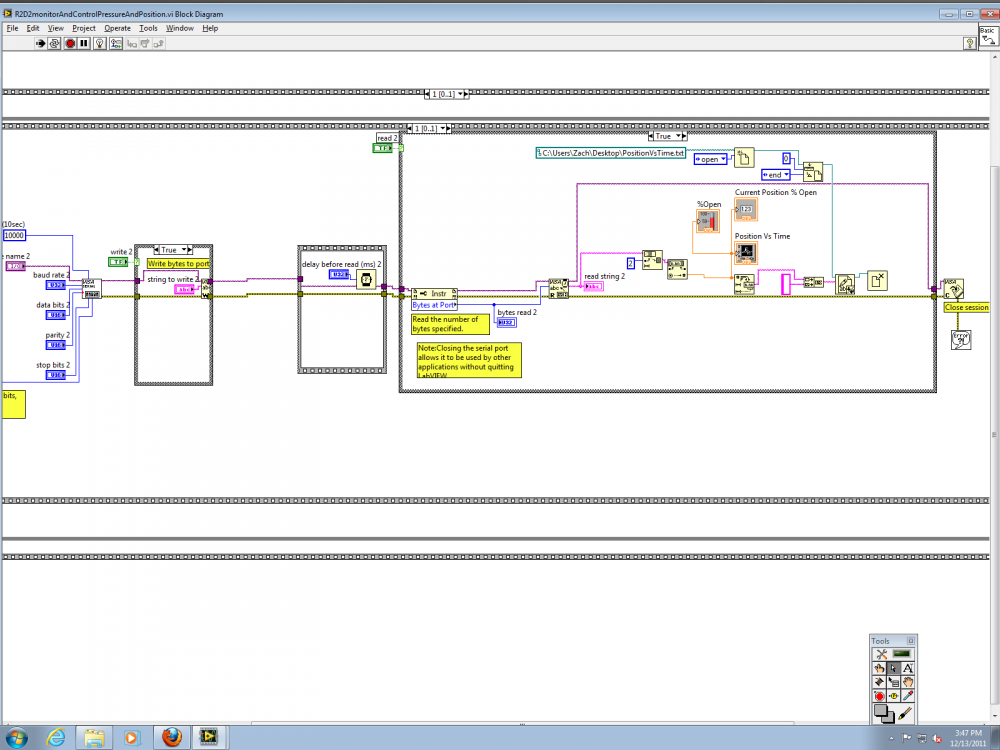
The vacuum pump was an Edwards XDS10 scroll pump borrowed from the Test AT-TPC chamber (though the test will be repeated for N2 with the newly purchased Agilent SH110 scroll pump. The chamber is an old welding-test chamber borrowed from the NSCL welding group (affectionately called R2D2) and has an internal volume of ~590 liters. N2 was taken from the NSCL LN2 boil-off lines, Argon was procured in a DOT3AA-2400 size K cylinder from the welding group's supply at the NSCL (which contains 8200 NTP-liters, thus allowing for 27 hours of operation with a 5 liter per minute flow), and Helium was procured in a DOT3AA2015 size A cylinder from Brad Barquest at the NSCL (which contains 6050 NTP-liters, allowing for 20 hours of operation with a 5 liter per minute flow). Gas was input to the chamber at 5 liters per minute (+-0.5 for N2 and Ar,+-1 for He). Pressure control was performed by the MKS T3BiA butterfly valve using the MKS 622A baratron. The communication with the T3BiA was performed using a specialized set of commands (a more complete list is here) and was automated using LabView (with a program titled R2D2monitorAndControlPressureAndPosition.vi). Screen-shots of the LabView program's display/control panel and base code are shown in the following two images.
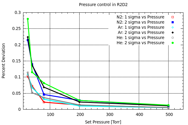
Both Model Based and PID pressure control were used to control chamber pressure. PID was found to have the best performance, and thus these results are quoted below. We used a phase of 1.5 and gain of 5. Results were analyzed by creating a histogram of percent deviation from the set-point pressure at the 1σ and 2σ level. The percent deviation histogram is not Gaussian, thus 1 and 2σ limits are determined by integration of the deviation histogram and the number quoted is the higher of the upper and lower deviations. E.g. We integrate from the mean up in deviation until we include 34.4% of the histogram area for the upper 1σ and from the mean down in deviation until we include 34.4% of the histogram area for the lower 1σ. Data was taken at set-point pressures: 25, 40, 80, 200, and 500 Torr. Our results are shown in the following image.
Our figure of merit is the percent deviation at the 2σ limit. We find similar qualitative trends in percent deviation as a function of pressure. Ultimately we find we are only able to control the set pressure to 0.1% deviation at pressures at and above 80Torr.
Compression
We will test the ability of our chosen compressor, the Gast MAAV109-MB diaphragm, to compress various gases. Ultimately we would like to determine the output pressure of the compressor as a function of input pressure and flow rate. We also need to determine the pressures reached in between the scroll pump and diaphragm compressor to be sure we do not have unsafe pressure build-ups. Practically we do not have enough pressure gauges to monitor the pressure at each point.
Measuring the post-compressor pressure is not necessarily well defined as pressure is defined in a given volume. However, the difference between outlet pressure and atmospheric pressure could be determined by measuring the flow rate through a tube of given conductance. This is via the relation: C = Q/dP, where C is the tube conductance, Q is the throughput (Q=PV/t), and dP is the difference between pressure at the beginning and end of the tube (keeping in mind the post-tube pressure is atmospheric). For our case the Hagen-Pouiselle equation will work fine.
A possible test set-up would look like the following image, with the ideal case of having gauges which communicate with our computer.
The pressure gauge connected to the test chamber will be the MKS 622A Baratron. The other pressure gauges do not exist yet. For the short term we will use a digital pirani gauge to read the pressure by eye. In this case we would place gauges in the different positions to do the various tests:
- MKS baratron connected to test chamber, pirani gauge in between pump and compressor (to see scroll pump compression & monitor for unsafe pressure build-ups)
- MKS baratron in between pump and compressor, pirani gauge connected to test chamber (to see how compressor inlet pressure is varying)
To Do
There is still a lot to do as of yet. Near-future items are:
- test the diaphragm compressor (which ships 8/31)
- settle on the pneumatic valves to use
- draw the system in the IGC-II configurator
- design our CompactRIO using NI's build tool
- estimate total system volume to see if 3He is viable
- if the compressor is sufficient, purchase purifiers to test their pressure drop as a function of flow and inlet pressure
- purchase mass-flow controllers
Who to Contact
For questions, comments, and suggestions regarding the AT-TPC gas handling system please email meisel(at)nscl(dot)msu(dot)edu, or stop by office W131 NSCL.

