Table of Contents
Timing
In a typical S800 experiment, there are different time-of-flight (ToF) measurements that can be used to identify the fragments of interest. The most common timing-signal sources used are the RF cyclotron (vetoed by the B6 output from the ULM Trigger module); the thin plastic scintillator at the A1900 focal plane box (XFP); the thin plastic scintillator at the S800 Object station (OBJ), and the S800 FP scintillator (E1) with two signals, one from the “up” and one from the “down” photomultipliers.
Although it is possible to measure the ToF between any pair of timing sources, there are three “standard” measurements provided to any experiment, namely, between the cyclotron and the S800 FP (RF-FP); between the A1900 FP and the S800 FP (XFP-FP); and between the S800 OBJ and FP (OBJ-FP). These ToFs are electronically recorded in a Phillips 7186 TDC, a Mesytec TDC (MTDC), and a group of Ortec 566 TACs, all them located in the electronic racks in S3, near the FP box.
Although the timing reference (“start”) in the all the ToF modules is given by the FP scintillator E1 up, the electronic path from the detector to each module is different (see main electronics diagram for more details).
Some important things to know about each of these modules:
MTDC
- This module has multi-hit capabilities. After a trigger signal from the FP scintillator is sent to the MTDC, a matching window is open. During this window, the MTDC will record any hit received on each channel
- The multi-hit capability is limited by the 160-ns conversion time of each channel, i.e. multiple events arriving to one given channel must be separated by at least 160 ns, in order to be correctly recorded by the module
- Before getting into the MTDC, the OBJ, XFP, and E1 up signals go through a Mesytec CFD (MCFD) in the S3 electronic racks
- The OBJ signal into the MCFD comes directly from the detector via S3 patch panel #94
- The XFP detector signal is sent to a CANBERRA CFD 454 CFD in data U6 (patch panel #1 from data U1). The output from the CFD is then sent back to the MCFD in S3 via patch panel #70
- The MTDC timing signals do not require external delay adjustments because the matching window is sufficiently wide
- The width and delay of the matching window can be changed in file vmusbdaqconfig.tcl in directory /user/s800/s800daq/Scripts
- The S800 SpecTcl used for online analysis calculates the OBJ-FP and XFP-FP ToFs by substracting the E1 up time (e.g. MTDC channel 0) to the OBJ time (MTDC channel 3) and the XFP time (MTDC channel 2). (Note that a better way to calculated these ToFs should use the average time E1_up and E1_down.)
- Note that the same flat ribbon cable connected to the MTDC is also feeding the scaler module. Thus, the 16 channels in the MTDC are exactly the same as channels 16-31 of the scaler module
- Copies of the timing signals from XF and OBJ used for the TAC ToF were included in channels 8 and 9 of the MTDC (also the scaler)
- The table below lists the MTDC channels:
| Ch. name | Ch. number | Electronic path (from detector) |
|---|---|---|
| E1 up | 0 | LeCroy Var. ampl. → Mesytec MCFD ch #0 → ECL-NIM → Fan in/out → Fan in/out → Fan in/out → Gate Generator → NIM-ECL |
| E1 down | 1 | LeCroy Var. ampl. → Mesytec MCFD ch #1 → ECL-NIM → Fan in/out → NIM-ECL |
| XFP | 2 | Patch #1 (dU6) → CANBERRA CFD (dU6) → Patch #70 → Fan in/out → Mesytec MCFD ch #2 → ECL-NIM → Fan in/out → NIM-ECL |
| OBJ | 3 | Patch #94 → LeCroy Var. ampl. → Mesytec MCFD ch #3 → ECL-NIM → Fan in/out → NIM-ECL |
| Free | 4 | |
| RF | 5 | Patch #69 → Fan in/out → Logic Unit → ECL-NIM → Fan in/out → NIM-ECL |
| CRDC1 Anode | 6 | Tennelec Ampl. → CANBERRA CFD → ECL-NIM → Fan in/out → NIM-ECL |
| CRDC2 Anode | 7 | Tennelec Ampl. → CANBERRA CFD → ECL-NIM → Fan in/out → NIM-ECL |
| XFP | 8 | Patch #1 (dU6) → CANBERRA CFD (dU6) → Patch #70 → Fan in/out → NIM-ECL |
| OBJ | 9 | Patch #54 (dU6) → CANBERRA CFD (dU6) → Patch #62 → Fan in/out → NIM-ECL |
| Free | 10-11 | |
| Hodosc. OR | 12 | Splitter att. → CANBERRA CFD → Fan in/out → NIM-ECL |
| Free | 13, 14 | |
| E1 up | 14 | LeCroy Var. ampl. → Mesytec MCFD ch #0 → ECL-NIM → Fan in/out → Fan in/out → Fan in/out → NIM-ECL |
| E1 up | 15 | LeCroy Var. ampl. → Mesytec MCFD ch #0 → ECL-NIM → Fan in/out → Fan in/out → NIM-ECL |
| II PPAC2 anode | 16 | Mesytec MCFD2 ch #0 |
| II PPAC2 down | 17 | Mesytec MCFD2 ch #1 |
| II PPAC2 up | 18 | Mesytec MCFD2 ch #2 |
| II PPAC2 right | 19 | Mesytec MCFD2 ch #3 |
| II PPAC2 left | 20 | Mesytec MCFD2 ch #4 |
| II PPAC1 anode | 21 | Mesytec MCFD2 ch #5 |
| II PPAC1 down | 22 | Mesytec MCFD2 ch #6 |
| II PPAC1 up | 23 | Mesytec MCFD2 ch #7 |
| II PPAC1 right | 24 | Mesytec MCFD2 ch #8 |
| II PPAC1 left | 25 | Mesytec MCFD2 ch #9 |
The multi-hit capability requires some special attention. Let's imagine a situation where the rate from OBJ detector is much higher than from the FP detector. During this window, the MTDC will record one hit from the FP scintillator (E1 up, which SpecTcl uses as the start ToF reference) and multiple hits from the OBJ scintillator (stops). As a results, SpecTcl will generate an array of OBJ-FP ToFs called s800.fp.vmetdc.obj.i, where i=0 stands for the first hit, i=2 second hit and so on (the corresponding array for XFP-FP TOF is s800.fp.vmetdc.xfp.i).
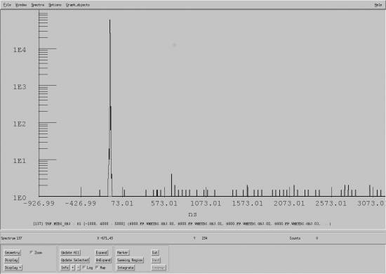
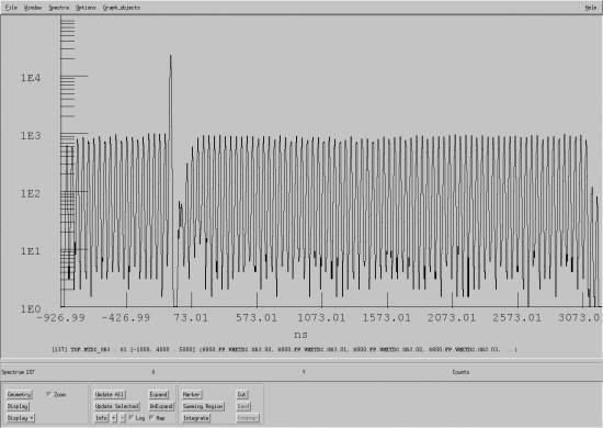
At moderate rates, or in an unreacted-beam setting, the first hit typically provides the “good” ToF (i.e. start and stop signals come from the same event in a given RF cycle). This is seen as a sharp single peak in the first figure below (showing a SpecTcl “gamma” spectra with all the hits from the array s800.fp.vmetdc.obj.i included). However, in a reaction setting (where the rates in the XFP and OBJ detectors are much higher than in the E1 up detector), the same spectrum will show multiple peaks (see next figure below); a very intense one corresponding to the “good” ToF (start and stop coming from the same event in the RF cycle), and many lower ones coming from ToFs generated by “random” coincidences between the start signal from E1 up and the OBJ stops generated from previous or later RF cycles.
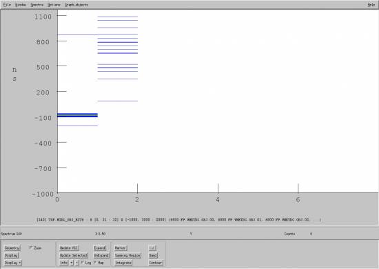
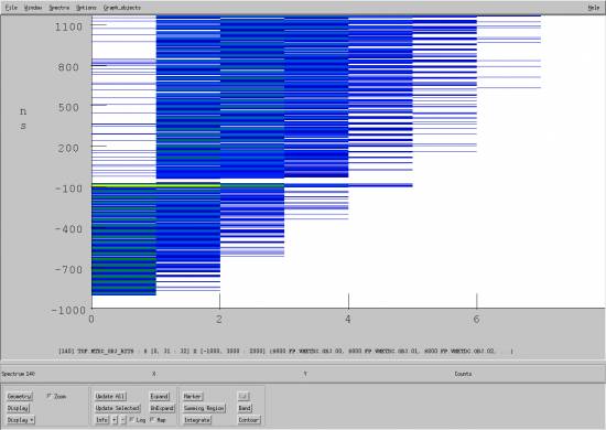
The two figures below show summary spectra with the OBJ-FP ToF (vertical axis) vs. hit number (horizontal axis). The first spectrum was recorded in an unreacted-beam setting, and the next one corresponds to a typical reaction setting. Note that in the former case, the “good” ToF peak (at ~-77 ns) is always given by the first hit, whereas in the later case, the good ToF (~-77 ns) can be given by any of the first five hits.
Tennelec TACs
- Unlike the MTDC and Phillips TDC, there is no TAC for the RF-FP ToF
- Before going to their corresponding TAC, the OBJ and XFP detector signals are sent to a CANBERRA CFD 454 CFD in data U6 via patch panel #54 and #1, respectively
- The OBJ output from the CANBERRA 454 CFD is sent to the stop of OBJ-FP TAC via patch panel #62
- The XFP output from the CANBERRA 454 CFD is sent to the stop of XFP-FP TAC via patch panel #70
- The table below lists the OBJ-FP TAC channels:
| Signal | Ch. ID | Electronic path (from detector) |
|---|---|---|
| S800 trigger | start | LeCroy Var. ampl. → Mesytec MCFD ch #0 → ECL-NIM → 4x Fan in/out → Logic Unit→ 300 ns delay |
| OBJ | stop | Patch #54 (dU6) → CANBERRA CFD (dU6) → Patch #62 → Fan in/out |
- The table below lists the XFP-FP TAC channels:
| Signal | Ch. ID | Electronic path (from detector) |
|---|---|---|
| S800 trigger | start | LeCroy Var. ampl. → Mesytec MCFD ch #0 → ECL-NIM → 4x Fan in/out → Logic Unit |
| XFP | stop | Patch #1 (dU6) → CANBERRA CFD (dU6) → Patch #70 |
Phillips TDC
ATTENTION: Since the end of the GRETINA-2017 campaign, this module is no longer used
- Before going to the TDC, the OBJ and XFP detector signals are sent to a CANBERRA CFD 454 CFD in data U6 via patch panel #54 and #1, respectively
- The TDC start is provided by the ULM trigger module. Since the delay of the S800 trigger may be adjusted during tuning of the S800 (XDT), the stop signals (e.g. from OBJ or XFP) need to be re-adjusted so that the ToF fits into the 400-ns range of the TDC. This is done manually for OBJ and XFP, and remotely via XLM delay module (operated by the Delay GUI) for other timing signals
- The OBJ output signal from the CANBERRA 454 CFD is delayed with the low-noise delay boxes in data U6, and sent to the TDC via patch panel #67
- The XFP output signal from the CANBERRA 454 CFD is delayed with the low-noise delay boxes in data U6, and sent to the TDC via patch panel #66
- SpecTcl calculates the OBJ-FP and XFP-FP ToFs by substracting the E1 up time (channel 8) to the OBJ time (channel 14) and the XFP time (channel 15)
- The table below lists the TDC channels:
| Ch. name | Ch. number | Electronic path (from detector) |
|---|---|---|
| E1 up | 0 | LeCroy Var. ampl. → Mesytec MCFD ch #0 → ECL-NIM → 2x Fan in/out → NIM-ECL → XLM Delay |
| E1 down | 1 | LeCroy Var. ampl. → Mesytec MCFD ch #1 → ECL-NIM → Fan in/out → NIM-ECL → XLM Delay |
| Free | 2-7 | |
| S800 trigger | 8 | LeCroy Var. ampl. → Mesytec MCFD ch #0 → ECL-NIM → 3x Fan in/out → NIM-ECL → XLM Delay |
| Free | 9, 10 | |
| Secondary trigger | 11 | Fan in/out → NIM-ECL → XLM Delay |
| RF | 12 | Patch #69 → Fan in/out → Logic Unit → NIM-ECL → XLM Delay |
| OBJ | 13 | Patch #54 (dU6) → CANBERRA CFD (dU6) → Delay → Patch #67 → NIM-ECL → XLM Delay |
| XFP | 14 | Patch #54 (dU6) → CANBERRA CFD (dU6) → Delay → Patch #66 → Fan in/out → NIM-ECL → XLM Delay |
| Free | 15 |


